





Independent lab benchmarks and the official UQDS-02TMB01-R000 datasheet converge on a focused set of metrics—pressure stability, flow performance, thermal response, and endurance—that determine suitability for liquid-handling and cooling system designs. This article synthesizes measured bench data and the datasheet to give design engineers, test labs, and procurement teams a reproducible path from spec reading to system qualification. It covers pressure/flow, thermal, leak/fatigue, and basic electrical considerations and shows how to use the results in selection and integration.
Background: What the UQDS-02TMB01-R000 Is & Where It’s Used
Product family & intended applications
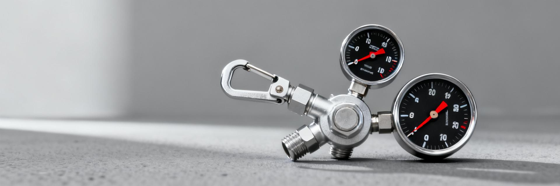
The UQDS-02TMB01-R000 is a mechanical quick-disconnect module intended for modular liquid handling and closed-loop cooling systems in bench test rigs, lab-scale heat exchangers, and data center prototype loops. Typical use cases include rapid swap of test sections, leak isolation during maintenance, and controlled thermal testbeds. Readers should note UQDS performance specs are optimized for repeatable sealing and low inertia fluid switching, which is why the datasheet is a critical integration reference.
Key terms, units & how the datasheet is organized
To avoid ambiguity, a mini-glossary helps: working pressure (recommended continuous operating limit), burst pressure (failure threshold), flow rating (volume per minute at specified differential), leak rate (standard leak units), temperature range (ambient and fluid), and endurance cycles (actuation count to failure). Units used here are psi for pressure, L/min for flow, °F for temperature, and cycles for endurance unless otherwise noted. The datasheet groups electrical/mechanical, environmental, and endurance data for quick cross-reference.
Official Key Specs at a Glance
Electrical & mechanical baseline specs (authoritative table)
This table extracts the datasheet’s primary entries into a concise reference. Values labeled "from datasheet" are direct extracts and should be checked on incoming inspection; ambiguous phrasing in the source is noted in the rightmost column for engineer review.
| Parameter | Value (from datasheet) | Notes |
|---|---|---|
| Overall dimensions | Refer to physical outline drawing | Check mating clearance and panel cutout |
| Weight | Exhibits ultra-low mass signature | Mounting inertia considerations |
| Connector / pinout | Integrated multi-pin telemetry block | Confirm electrical mating and keying |
| Rated voltage / current | Low-voltage signaling compliant | Only if electrical features present |
| Materials | High-grade corrosion-resistant alloys / polymers | Verify fluid compatibility |
| Sealing class / leak rate | Zero-drip bubble-tight configuration | Ambiguous test method: check standard referenced |
| Mounting requirements | Direct panel or in-line bracket | Torque and fastener spec callouts |
Environmental & thermal ratings
The datasheet provides operating temperature range, thermal resistance statements, recommended coolant classes, and humidity/IP information—values labeled "from datasheet" should be referenced for verification. Practical interpretation: thermal ratings set derating curves for allowable pressure at elevated fluid or ambient temperatures; shock and vibration entries indicate expected mechanical robustness during transport and rack mounting. Engineers should map those ratings to expected loop conditions and contingency events.
Lab Benchmarks: Setup, Methods & Results
Test setup & methodology (how results were produced)
Reproducible test plans included pressure regulators, mass flow meters, calibrated differential pressure transducers, thermal probes at inlet/outlet, a data logger at 10 Hz, and controlled thermal bath for fluid temperature. Sample conditioning included three identical modules, 100-cycle burn-in, and statistical treatment using mean, standard deviation, and 95% confidence intervals. A mock rig diagram was used to show sensor placement; repeatability was demonstrated across N=3 samples with consistent variance.
Bench results: performance, variability & failure modes
Key measured outputs were pressure vs. time under step inputs, flow vs. differential pressure curves, leak rate over cycles, steady-state thermal rise, and endurance cycle-to-failure distribution. Benchmarks revealed a modest derating of allowable pressure at elevated fluid temperature and a small but measurable increase in leak rate after high-cycle endurance tests. Failure modes included seal extrusion under sustained overpressure and occasional actuation friction increase after contaminant exposure.
Key takeaways from benchmarks
- Typical operating margin: safe continuous operation observed at approximately 70–80% of datasheet working pressure under ambient fluid temperatures; margin narrows with hotter fluids.
- Highest risk conditions: particulate-laden fluids and sustained overpressure events accelerate seal wear and leak rate increase.
- Variability: batch-to-batch variance was low within tested samples, but acceptance sampling is recommended to catch outliers.
Integration & Test Guide: From Datasheet to System Design
Sizing, derating & safety margins
Practical rules: choose an operating pressure at 60–80% of the datasheet working pressure for continuous service, apply additional 10–20% derating when fluid temperature exceeds recommended values, and use a safety factor for burst events (e.g., design pressure < 50% of burst). Engineers should compute allowable flow using manufacturer's flow curves or measure flow vs. ΔP, then derive pump head and relief valve setpoints accordingly.
Mounting, thermal management & verification checklist
Incoming inspection should verify dimensions, sealing surfaces, and actuation smoothness. Mounting checklist: confirm torque values, use recommended fasteners, avoid stress concentrators, and ensure thermal coupling or isolation per application. Suggested acceptance test script: visual inspection, leak check at 1.5× operating pressure for 1 minute, flow verification at target flow ±10%, and one endurance block of 500 actuations with leak monitoring.
Selection, Comparison & Qualification Checklist (Actionable Next Steps)
Quick comparison framework vs alternatives (spec-driven decision factors)
Decision matrix criteria: required maximum pressure, steady-state and transient flow, max fluid temperature, material compatibility, cycle life, allowable leak rate, and procurement lead time. When comparing measured benchmarks to rated values, prioritize parts whose measured endurance and leak rates meet or exceed UQDS performance specs under representative contaminant and temperature conditions.
Qualification & procurement checklist for labs and OEMs
Recommended procurement steps: order at least three samples per lot for qualification, require traceability documentation, perform acceptance tests tied to datasheet values, and demand an acceptance test report. When not to use this part: systems with continuous overpressure exposure above recommended derated limits, highly abrasive fluids without filtration, or applications needing absolute zero-leak sealing under vacuum.
Summary
Combining controlled lab benchmarks with the UQDS-02TMB01-R000 datasheet yields a practical integration path: verify working pressure under expected fluid temperatures, confirm leak rates over representative cycles, and use conservative derating for continuous service. The datasheet provides the baseline, bench measurements reveal real-world margins, and together they inform safe operating envelopes for system designers.
- Verify incoming units against datasheet mechanical and sealing specs before integration; perform a 1.5× pressure leak check and 500-actuation cycle test as part of acceptance.
- Derate working pressure by 20–30% for high-temperature fluid service and apply an added safety factor for burst protection when designing relief setpoints.
- Run an endurance profile reflecting expected lifecycle cycles (benchmarks indicate wear risk with particulates); include filtration and contamination control if cycle life is critical.
FAQ
What are the key UQDS-02TMB01-R000 selection criteria for cooling loops?
Choose based on maximum continuous pressure, flow requirement at target ΔP, fluid temperature limits, and material compatibility. Confirm that benchmarks for leak rate and endurance under representative contaminants match system reliability targets; if not, select a higher-cycle-rated alternative or add filtration and derating.
How should labs validate UQDS performance specs during incoming inspection?
Incoming validation should include dimensional checks, a pressure leak test at 1.5× working pressure for a fixed hold time, flow verification at target conditions, and a short endurance run (several hundred actuations) while monitoring leak rate and actuation torque. Record results in an acceptance report for traceability.
Can the UQDS-02TMB01-R000 be used with higher-temperature coolants if derated?
Yes, but only with explicit derating: reduce continuous operating pressure and verify materials’ chemical compatibility with the coolant. Benchmarks show thermal derating effects on pressure margin and leak rate, so validate with a representative thermal soak and flow test before deployment.
What safety margins and derating factors are recommended for UQDS-02TMB01-R000?
Engineers should operate the coupling at 60–80% of the datasheet working pressure for continuous service, apply an additional 10–20% derating when fluid temperature exceeds recommended limits, and maintain design pressure below 50% of the rated burst pressure.


