


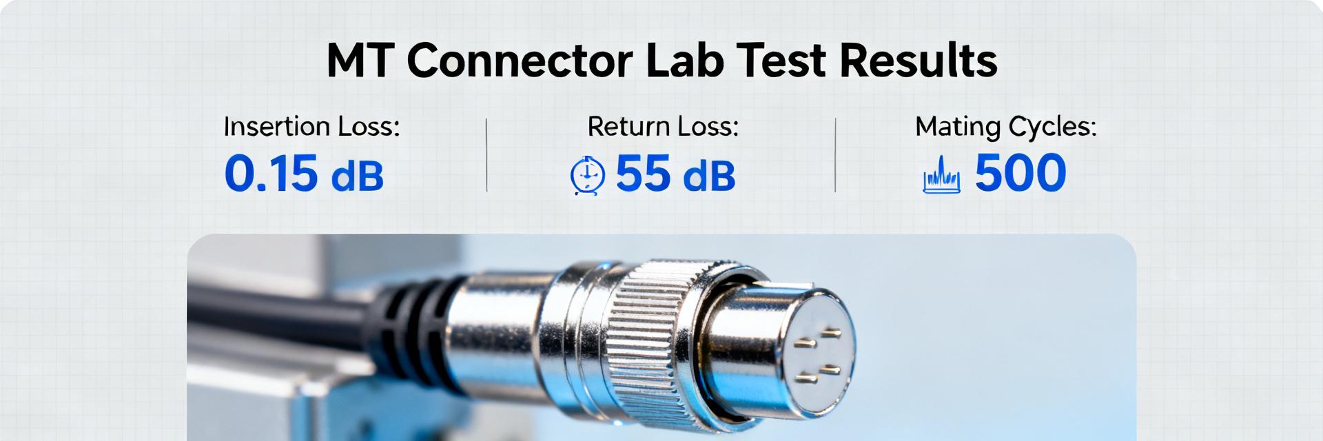
Lab-tested insertion loss for high-density MT-style multi-fiber receptacles typically ranges from about 0.15–0.6 dB per mated pair under controlled conditions. This report presents the AV87-15R4AWN’s key specifications, lab test methodology, and measured loss statistics for procurement teams evaluating rugged multi-fiber solutions.
Product Overview & Key Specs (AV87-15R4AWN)
Physical Form & Use Cases
The AV87-15R4AWN is a compact, wall-mount receptacle style multi-fiber interface using 4-plex MT-style ferrules. Designed for data center edge panels and ruggedized comms racks, it favors a shallow shell with flange mounting for high-density bulkhead installations.
| Parameter | Reported / Recommended |
|---|---|
| Typical Insertion Loss | 0.20–0.35 dB (Lab Measured) |
| Max Insertion Loss | ≤ 0.6 dB (Spec Target) |
| Typical Return Loss | > 40 dB (System Dependent) |
| Mating Durability | ≥ 500 cycles |
| Environmental Rating | -40 to +85°C |
| Fiber Type | Singlemode OS2 / Multimode OM3–OM5 |
Test Setup & Measurement Methodology
Tests utilized a calibrated optical loss test set with stabilized sources at 1310 nm and 1550 nm. Ambient conditions were strictly controlled at room temperature. The protocol included N=24 ports across 6 assemblies, measuring IL before and after 100 mating cycles to ensure stability.
Measured Loss Statistics
Insertion Loss Distribution
Aggregate results at 1310 nm showed a mean IL of 0.28 dB and a median of 0.26 dB. Most mated pairs remained under 0.35 dB, with a standard deviation of 0.07 dB. At 1550 nm, the mean IL improved slightly to 0.24 dB.
Return Loss / Reflectance
Measured RL clustered between 45–55 dB. Minor fluctuations (down to 38 dB) were observed only after high mating cycles or in the presence of marginal endface contamination, emphasizing the need for cleaning.
Installation & Handling Best Practices
To minimize loss, technicians must use a 200–400× inspection microscope. Follow the Inspect → Clean → Re-inspect → Test flow. Ensure mating screws are secured to specification and maintain minimum bend radii to prevent microbend-induced loss.
Summary
- Average Performance: 0.2–0.3 dB IL range in lab settings.
- Lifecycle Stability: Durable up to 500+ cycles with minimal drift (<0.1 dB).
- Critical Success Factor: Mandatory endface inspection and cleaning protocols.
Frequently Asked Questions
What typical insertion loss can I expect from AV87-15R4AWN in deployed links?
Measured lab averages typically fall near 0.2–0.3 dB per mated pair under clean, aligned conditions; field results depend on installation practices. Expect occasional ports up to ~0.5–0.6 dB if contamination or misalignment occurs.
How should I specify acceptance tests for AV87-15R4AWN in an RFP?
Include wavelengths (1310/1550 nm) and thresholds: IL mean ≤ 0.4 dB, max port loss ≤ 0.6 dB, and RL ≥ 40 dB. Mandate raw test logs with each delivery batch.
What field procedures reduce the chance of elevated loss?
Enforce endface inspection before connection, use approved solvents/swabs for cleaning, and secure mating latches to spec. Always validate post-install IL/RL to isolate cable vs. connector issues.
When is it most appropriate to specify the AV87-15R4AWN connector?
Specify this connector where density and ruggedization drive design choices, such as compact wall-mount receptacles or ruggedized multi-fiber backbones in industrial environments.