





Accurate datasheets for a UQD quick disconnect are the single most effective guard against unexpected leaks, system downtime, and procurement errors. Engineers and buyers rely on datasheet entries—pressure, temperature, flow coefficient, leak rates, and cycle life—to match coupling performance to system duty. This introduction outlines what to verify on a UQD quick disconnect datasheet and sets expectations for a clear, actionable breakdown of every spec entry.
Datasheets consolidate measured limits and tested results; misreading them or omitting a derating step is a common root cause of field failure. This guide translates typical datasheet language into concrete checks: definitions and nomenclature, mechanical and fluid limits, material and seal compatibility, test methods and reliability indicators, and a stepwise procurement checklist you can apply before issuing a PO.
1 — What a UQD quick disconnect datasheet is and why it matters (background)
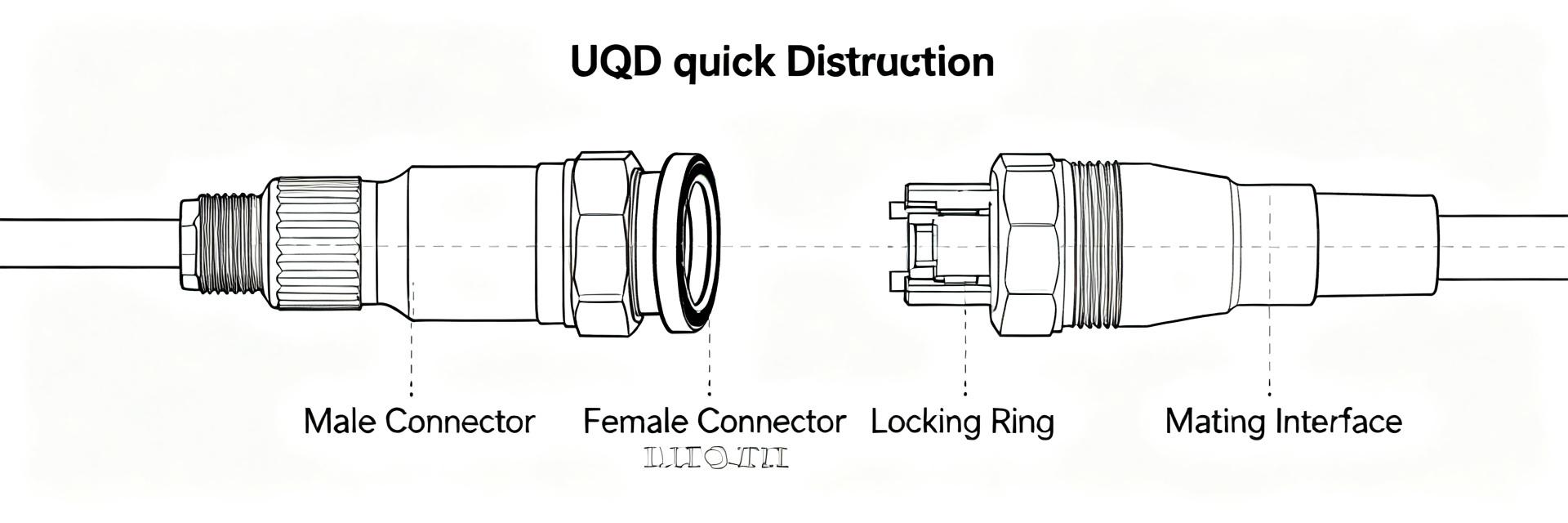
Key terms and interface nomenclature
Point: Key terms on a datasheet codify performance expectations. Evidence: Typical labels include working pressure (rated continuous), burst pressure (destructive test), nominal diameter (DN), Cv or flow coefficient, declared leak rate, and cycle-life metrics. Explanation: Understanding naming conventions—male/female plug/socket, thread style, and color coding—lets teams map part numbers to system ports and seal families rather than guessing compatibility.
| Term | Typical meaning |
|---|---|
| Working pressure | Continuous allowable system pressure |
| Burst pressure | Destructive limit, safety reference |
| Nominal diameter (DN) | Internal flow diameter for Cv lookup |
Glossary example: Part-number segment "DN05-SS-FKM" → DN05 nominal, stainless-steel body, FKM seal.
Typical sizes and application families
Point: UQD sizes cluster by nominal diameter and intended application. Evidence: Common DN values span DN02–DN10; smaller DN02–DN04 suit sensor coolers and instrument lines while DN06–DN10 are common for server liquid cooling and thermal management. Explanation: Choosing the correct DN balances allowable flow and acceptable pressure drop—oversized couplings add cost and footprint, undersized couplings increase head loss and potential cavitation.
| DN | Typical max flow (typical example) | Applications |
|---|---|---|
| DN02 | 0.1–0.4 L/min | Instrument cooling, test lines |
| DN05 | 1–4 L/min | Board-level cold plates, small loops |
| DN10 | 6–15 L/min | Rack-level thermal management |
2 — Mechanical and fluid specifications: limits you must verify (data analysis)
Pressure and temperature ratings (what to look for)
Point: Pressure and temperature specs drive design margins. Evidence: Datasheets list working (rated) pressure and burst pressure; designers should apply a safety margin—commonly designing systems to operate below about 70–80% of rated working pressure depending on risk tolerance. Explanation: Temperature shifts alter seal properties and metal strength; require continuous operating range and short-term extremes, and apply pressure derating at elevated temperatures per datasheet notes.
| Spec | Displayed on datasheet |
|---|---|
| Working pressure | e.g., 100 psi (typical example) |
| Burst pressure | e.g., 400 psi (typical example) |
| Temp range | -40°C to +120°C (typical example) |
Flow performance and pressure drop (Cv, flow curves)
Point: Cv and flow curves quantify head loss. Evidence: Datasheets include Cv or plotted flow vs. ΔP curves allowing conversion between pressure drop and volumetric flow. Explanation: To size a coupling, extract Cv from the datasheet or curve and calculate flow: Q = Cv * sqrt(ΔP/(SG)), where SG is specific gravity. Use the curve to confirm acceptable ΔP at target flow and system pump capability.
Sample calculation (typical example): Cv = 0.8, ΔP = 2 psi, SG = 1 → Q ≈ 0.8 * sqrt(2) ≈ 1.13 GPM (convert units as needed).
3 — Materials, seals and fluid compatibility (data analysis / method)
Material construction and corrosion limits
Point: Body material selection affects corrosion resistance, weight, and cost. Evidence: Datasheets declare materials—stainless steels, plated alloys, or engineered polymers—and reference corrosion limits in particular chemistries. Explanation: Match material to coolant chemistry. For deionized water select stainless alloy with passivation; for glycol mixtures consider seal compatibility and potential galvanic coupling with other system metals; document material certificates when corrosion risk is non-trivial.
| Material | When to choose |
|---|---|
| Stainless steel | High corrosion resistance, critical systems |
| Plated alloy | Cost-sensitive, moderate exposure |
| Polymer | Low-pressure, weight-sensitive applications |
Seal types and chemical/temperature compatibility
Point: Seal elastomer determines chemical and thermal boundaries. Evidence: Common seal materials include FKM (fluorocarbon), EPDM, PTFE and specialty elastomers with distinct limits. Explanation: Follow a compatibility-check workflow: identify fluid chemistry and operating temperature, cross-check seal chemical resistance and temperature limit, then apply pressure/temperature derating from the datasheet to confirm long-term integrity.
- Identify fluid and concentration.
- Reference seal compatibility chart on datasheet.
- Confirm temperature and pressure derating rules.
4 — Tests, leak limits and reliability data (method / case study)
Standard test methods and acceptance criteria
Point: Datasheets report test methods and thresholds. Evidence: Typical entries include pressure test protocol, burst test result, cycle-life count, and declared leak-rate measured by helium sniff, bubble, or vacuum methods. Explanation: Expect a test-results table showing test conditions and acceptance criteria; request reported method when leak rates are crucial to system cleanliness or non-spill requirements.
Failure modes, wear mechanisms and expected service life
Point: Common failures are predictable and detectable. Evidence: Seal extrusion, particulate abrasion, corrosion, thread wear, and thermal cycling degradation are frequently cited. Explanation: Use an inspection checklist (visual seal condition, leak checks under pressure, torque and thread integrity) and adopt replacement triggers tied to cycle counts or any observed leakage, plus scheduled maintenance intervals documented in procurement.
5 — How to read a datasheet and specify the right UQD (method / action)
Step-by-step selection and specification checklist
Point: A reproducible checklist prevents specification gaps. Evidence: Essential checks include confirming system pressure/temperature, choosing DN and Cv for flow, selecting body material and seals, and specifying thread/port style plus required test reports. Explanation: Before PO: (1) record duty points, (2) match DN and Cv, (3) select materials and seals, (4) require pressure and leak-test certificates, and (5) request sample flow curves and material certificates.
- Confirm system max continuous pressure and temperature.
- Select DN to meet peak and transient flows (use Cv).
- Specify body material and seal elastomer with certificates.
- Require pressure, burst, leak-rate, and cycle-life test reports.
- Request dimensional drawing and installation notes.
Sample datasheet snippet and sample spec language for procurement
Point: Standardized procurement wording avoids ambiguity. Evidence: A compact procurement line captures required attributes and test deliverables. Explanation: Use the following template as a copy-paste spec to attach to RFQs and POs to ensure suppliers supply matching test documentation and certifications.
Sample spec (paste into PO): "UQD quick disconnect, DN05, stainless-steel body, FKM seals; rated working pressure 100 psi at 20°C (typical example); burst pressure ≥400 psi (typical example); Cv = 0.8 (typical example); tested to declared pressure and leak methods; continuous temp range -40°C to +120°C; supply pressure and material certificates and dimensional drawing."
Summary
Reading a UQD quick disconnect datasheet end-to-end prevents specification gaps that cause leaks and downtime. Verify pressure and temperature limits with conservative safety margins, confirm material and seal compatibility against coolant chemistry, and require test reports to substantiate declared limits. Use the checklist above to convert datasheet language into procurement-ready requirements.
- Verify working and burst pressure and apply a conservative safety margin when specifying system operating pressure and transient allowances to avoid overstress of seals or body.
- Confirm material and seal compatibility with actual coolant chemistry and operating temperature; request material and seal certificates to avoid corrosion and premature wear.
- Require test evidence: pressure, burst, leak-rate and cycle-life results with method declarations; ensure flow curves/Cv values match expected ΔP conditions.
Common Questions
What is the difference between working and burst pressure on a UQD quick disconnect?
Working (rated) pressure is the maximum recommended continuous service pressure; burst pressure is a destructive test limit indicating when the part fails. Design practice uses a safety factor: operate below the rated pressure by 20–30% or more depending on risk tolerance and transient conditions.
How do I convert Cv to flow rate for a UQD?
Extract Cv from the datasheet or curve, then use Q = Cv × sqrt(ΔP/SG) where Q is flow rate and SG is specific gravity. Convert units as needed for GPM/LPM; the datasheet curve lets you confirm acceptable ΔP at the target flow for system pump sizing.
Which seal materials work with glycol-based coolants?
Commonly chosen seals for glycol mixtures include EPDM and certain fluoroelastomers; compatibility varies with glycol type, concentration, and temperature. Always verify with the datasheet compatibility table and request manufacturer confirmation when system operating temperature or additives are outside standard ranges.
What are the primary failure modes for UQD couplings in liquid cooling loops?
Primary failure modes include seal extrusion due to overpressure, particulate abrasion on O-rings leading to micro-leaks, chemical degradation from incompatible coolants, and mechanical wear of the locking mechanism during frequent connect/disconnect cycles.


