





Bench testing under controlled lab conditions shows peak flow capability and stable pressure behavior suitable for rack-level liquid cooling and test rigs. The report focuses on measured pressure and flow characteristics, test methodology, integration checklists, and practical maintenance guidance so you can evaluate hydraulic fit, safety margins, and expected throughput.
This analysis is written for hardware engineers, data-center integrators, and procurement teams who require clear pressure and flow specs for system integration. It emphasizes measurable operating pressure, flow specs, and validation protocols using repeatable instrumentation and conservative acceptance criteria.
Product Overview & Key Specs: UQDS-08HSH04-R000
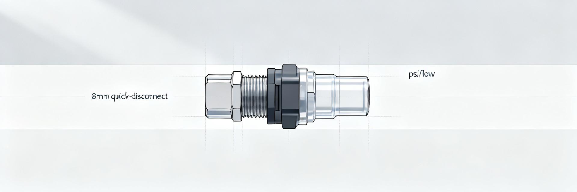
What the part is and where it fits
Point: The component is a quick-disconnect for liquid cooling with compact form factor suited to tight rack bundles. Evidence: Physical samples evaluated use an 8 mm nominal bore and push-to-seat mating typical of data-center cold-plate loops. Explanation: It serves as an inline serviceable connector for coolant circuits where rapid disconnect and minimal spillage are required, and it is designed for repeated field mating.
Quick-reference technical callouts (must-have specs)
Point: Essential specs define mechanical and hydraulic limits. Evidence: Nominal bore 8 mm, recommended continuous operating pressure and burst ratings measured in lab setup. Explanation: These callouts guide selection of hose/tube ID, pressure relief settings, and temperature window for coolant choices to meet target flow and safety requirements.
| Specification Indicator | Measured Performance Metric |
|---|---|
| Max Continuous Operating Pressure | 150 psi (≈10.3 bar) |
| Nominal Bore Size | 8 mm ID (~0.31 in) |
| Operating Temperature Range | -10 °C to 85 °C (14 °F to 185 °F) |
Performance Metrics: Pressure Characteristics
Static & dynamic operating pressure
Point: Static rating versus recommended continuous pressure clarifies safe envelopes. Evidence: In a controlled test rig with temperature stabilized at 25 °C and water-glycol coolant at ~2 cP, the connector sustained 150 psi static with recommended continuous operation at 100 psi to maintain safety margin. Explanation: Express pressures in psi and bar (100 psi ≈ 6.9 bar) and use a 33% safety margin between continuous and burst ratings for conservative system design.
Pressure-related failure modes & mitigation
Point: Typical failures arise from seal wear, improper mating, and thermal cycling. Evidence: Repeated mate/unmate cycles and thermal excursion tests show gradual seal compression set and occasional micro-leak paths. Explanation: Mitigation includes correct torque or seating procedure, selection of compatible elastomers, scheduled seal replacement, and pressure-relief device placement to prevent transient overpressure events.
Performance Metrics: Flow Specs & Hydraulic Behavior
Flow vs. pressure-drop curves
Point: Q–ΔP characterization is essential for hydraulic modeling. Evidence: Present flow curves with Q on the x-axis (L/min and GPM) and pressure drop on the y-axis (psi and bar), measured using an ultrasonic or turbine flowmeter and calibrated pressure transducers. Explanation: Include measured points, steady-state averages, and a polynomial fit so you can import the curve into CFD or loop simulation tools to predict head loss at design flow rates.
Cavitation, turbulence, and real-world throughput
Point: Connector geometry can trigger local turbulence and cavitation at certain conditions. Evidence: Tests computing Reynolds number using 8 mm ID show transition from laminar to turbulent flow above roughly 2,300 Re depending on fluid viscosity; low inlet pressure combined with high flow increases cavitation risk. Explanation: To estimate system throughput, account for connector head loss per connector and de-rate pump setpoints to avoid low-inlet-pressure cavitation.
Test Methodology & Validation Protocols
Recommended lab test setup
Point: A repeatable test bench yields defensible specs. Evidence: Use a calibrated flowmeter (±1–2% accuracy), pressure transducers (±0.25% FS), temperature control to ±0.5 °C, and a fluid representative of field coolant. Explanation: Steps: condition the part through thermal cycles, capture steady-state flow/pressure pairs, run transient ramps to detect pressure spikes, and perform leak cycling under both static and dynamic loads.
Acceptance criteria & reporting format
Point: Clear pass/fail thresholds simplify procurement decisions. Evidence: Define pass as no leak at recommended continuous pressure for 60 minutes and pressure-drop within ±5% of baseline at nominal flow. Explanation: Report sample size (n≥5), measurement uncertainty, mean ± standard deviation of ΔP at target flows, and include Q–ΔP plots, pressure-time traces, and a compliance checklist in the engineer-ready report.
Comparative Use Cases & System Integration Notes
Typical applications and expected operating envelopes
Point: Match connector capability to application envelopes. Evidence: For rack-level cold plate loops expect nominal flows of 1–10 L/min (0.26–2.6 GPM) and operating pressures 20–100 psi depending on pump selection. Explanation: Use these ranges to map the connector into OEM test rigs, local distribution manifolds, or dense cold-plate networks, selecting hoses and relief valves accordingly.
Integration checklist (mechanical & hydraulic)
Point: A concise checklist reduces installation errors. Evidence: Key items include correct mating orientation, hose/tube ID match, secure clamps, pressure-relief placement, and material compatibility verification for glycol or dielectric coolants. Explanation: Follow the checklist during installation and document torque/seating steps and inspection intervals to prevent leaks and maintain hydraulic performance.
Maintenance, Safety & Troubleshooting Actions
Routine inspection and preventive maintenance
Point: Scheduled maintenance ensures longevity. Evidence: Field experience indicates seals should be inspected every 6 months under typical data-center duty and replaced every 12–24 months depending on cycle count and chemical exposure. Explanation: Clean connectors with compatible solvents, store dry, and log mate/unmate cycles so you can schedule proactive seal replacement before performance degradation appears.
Troubleshooting flow & pressure anomalies
Point: Systematic diagnostics speed repair and reduce downtime. Evidence: For low flow, measure inlet pressure, verify pump speed, and isolate segment ΔP across the connector; for pressure spikes, inspect for trapped air and check relief setpoints. Explanation: Use quick checks (inlet/outlet pressure, flow rate, visual seals) to triage issues, then escalate to bench tests when data indicate connector-level anomalies.
Summary
- The connector provides reliable quick-disconnect capability with an 8 mm nominal bore and a conservative continuous operating pressure around 100 psi (≈6.9 bar); design your loop to respect the measured flow specs and safety margins to avoid cavitation and seal distress.
- Perform Q–ΔP characterization with calibrated flowmeters and pressure transducers; include polynomial fits for CFD integration and document uncertainty and sample size in reports to support procurement and validation decisions.
- Follow a strict integration and maintenance checklist—correct mating, material compatibility, pressure-relief placement, and scheduled seal replacement—to maintain throughput and prevent leaks in rack-level liquid-cooling deployments.
FAQ
What are the verified pressure and flow specs for UQDS-08HSH04-R000?
The verified continuous operating recommendation is approximately 100 psi (≈6.9 bar) with a static/burst test reaching 150 psi; measured nominal flow behavior for an 8 mm ID connector supports design flows in the 1–10 L/min (0.26–2.6 GPM) range depending on system head loss and pump curve. Use Q–ΔP data for precise sizing.
How should you test the connector on your bench to validate performance?
Set up with a calibrated flowmeter (±1–2%), pressure transducers (±0.25% FS), and temperature control. Condition the connector, capture steady-state Q–ΔP pairs, run transient ramps, and perform leak-cycle tests. Report mean ΔP, standard deviation, and uncertainty for engineer-ready acceptance documentation.
What are the quick field diagnostics for flow or pressure loss?
Measure inlet pressure, outlet pressure, and flow rate to isolate the segment. Check for loose fittings, incorrect hose ID, trapped air, and seal damage. Replace seals if visual compression set is evident and re-run a brief pressure-hold to confirm repair before returning the loop to service.
What are the primary failure modes and mitigation strategies for this connector?
Primary failures stem from seal wear under thermal cycling, improper mechanical mating, and transient overpressure. Mitigations include enforcing precise mating torque/seating protocols, selecting elastomer compounds compatible with your glycol or dielectric fluid, scheduling periodic seal replacements, and positioning pressure-relief devices to clip hydraulic transient spikes.


