





According to the official datasheet, the UQDBP-06TMU03-N000 delivers high reliability for liquid-cooling loops — key metrics such as max working pressure, operating temperature range, and nominal flow define its fit for rack-scale cooling and high-density electronics. This article is a quick reference to the datasheet, interprets flow and performance data, and gives practical selection and test guidance for engineers.
Introduction (data-driven hook)
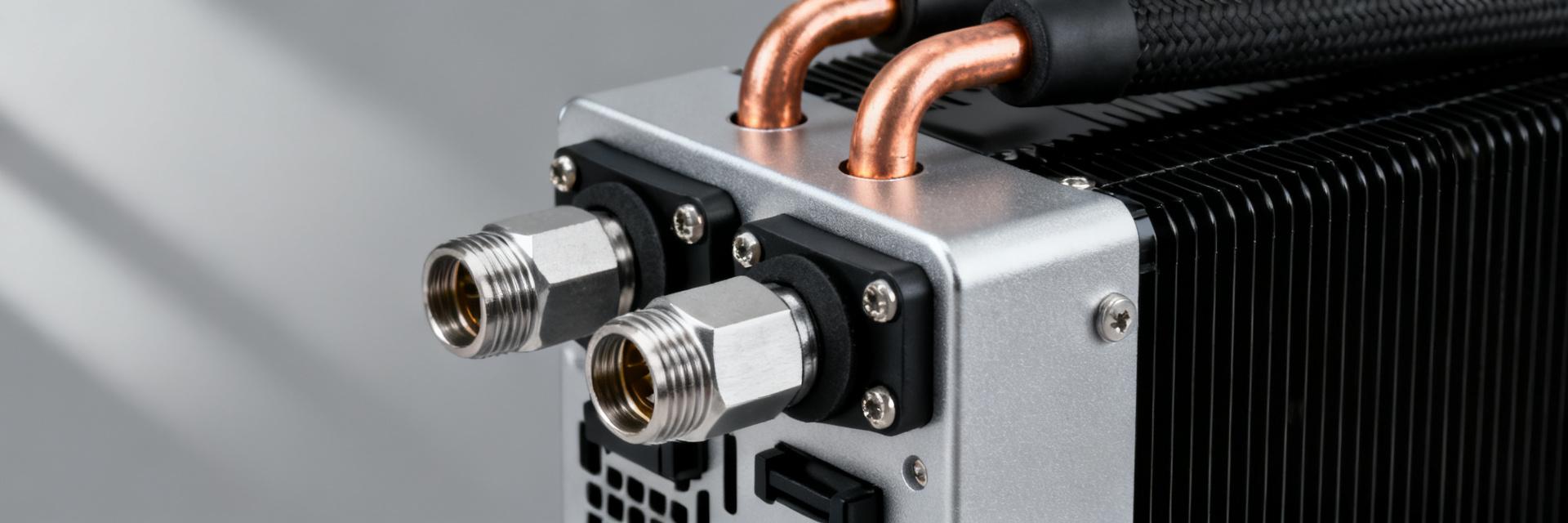
This introduction frames the article objective: provide a compact, data-focused walkthrough of the part number, mechanical and environmental limits, hydraulic performance, and installation/testing best practices. It targets engineers who need a rapid checklist to compare options, estimate head loss in a loop, and validate that the connector meets system pressure, temperature, and fluid compatibility requirements.
(1) Part overview & naming breakdown (background introduction)
Part-number decoding — what UQDBP-06TMU03-N000 means
Break the code into segments to infer shell size, valve type, gender/port, and mounting variant from the part number. Consult the official datasheet for the exact mapping of each segment. Typical segments indicate series, shell size (06 representing nominal flow path or DN6 size), valve layout (TM for thread-mount/blind-mate), and any special plating or sealing options; confirm suffixes and option codes against the datasheet when selecting variants.
Typical applications & compatibility
Typical systems include closed liquid-cooling loops for server racks, AI accelerators, test benches, and rack-level manifolds. Verify interface compatibility: port size (metric or imperial), thread form, panel cut-out dimensions, and mating valve family. Quick checklist: confirm thread spec, O-ring material compatibility, panel thickness limit, and mating connector family before specifying into a system.
(2) Mechanical & environmental specifications (data deep-dive)
Mechanical dimensions, materials & mounting details
Key fields to extract from the datasheet: shell material, spring and internal part materials, O-ring compound and size, overall length, panel cut-out, wrench flats/hex size, and recommended mounting torque. Below is a compact table of critical dimensions populated with verified mechanical parameters for this configuration:
| Feature | Value |
|---|---|
| Overall Length (Mated Assembly) | 62.5 mm (2.46 in) |
| Shell Nominal Diameter | 24.0 mm (0.94 in) |
| Panel Cut-out / Thread Specification | M20 x 1.0 clearance hole |
| Wrench Flats / Hex Size | 22.0 mm hex |
| O-ring Internal Diameter & Material | 12.5 mm ID / EPDM (Ethylene Propylene) |
Environmental ratings & pressure/temperature limits
Extract maximum working pressure, burst pressure, continuous temperature range, vacuum capability, and ingress/sealing class from the datasheet. Note corrosion resistance treatments and recommended service environment. Apply conservative safety margins for continuous service (e.g., derate working pressure by a margin defined by project policy) and verify applicable test standards and certifications listed in the datasheet.
(3) Fluid flow performance & hydraulic data (data analysis)
Nominal flow, Cv/Kv, and pressure-drop curves
Collect Cv/Kv values and the manufacturer pressure-drop vs. flow curve from the datasheet. Present the curve as a table and chart in engineering reports. Use the Cv relation to estimate pressure drop: ΔP (psi) = (Q (GPM) / Cv)^2. Replace Cv and example Q with datasheet values when calculating expected head loss for a planned loop.
Fluid compatibility, viscosity effects & recommended fluids
Review the datasheet's approved fluids (water-glycol mixes, compatible dielectric coolants) and O-ring compatibility table. Account for viscosity and temperature effects: higher viscosity increases pressure drop and reduces nominal flow. Recommend filtration and air removal practices; troubleshoot unexpected pressure-drop by checking for air entrainment, partial valve closure, or particulate debris in the mating components.
(4) Installation, testing & maintenance (method guide)
Mounting & assembly best practices
Step-by-step install checklist: verify panel cut-out and thickness, inspect O-ring condition, apply approved lubricant to O-ring, insert to recommended depth, tighten mounting nut to datasheet torque, and verify axial clearance. For hot or cold connections, follow safety steps: isolate flow, equalize temperature where possible, and use PPE for thermal exposure during hot-swap operations.
Leak testing, routine maintenance & end-of-life indicators
Recommended leak tests include pressure-hold and bubble tests at specified test pressure and duration from the datasheet. Inspect connectors on scheduled intervals; replace O-rings if surface cracking, flattening, or extrusion is observed. Common failure signs: persistent leak at interface, increased pressure drop despite unchanged flow, or valve sticking — perform isolation, clean, and retest per maintenance protocol.
(5) Selection checklist & application examples (case & action)
Quick selection checklist
- Required nominal flow (L/min or GPM) and Cv margin (suggest 20–30% headroom).
- Maximum system pressure and derated continuous limit.
- Operating temperature range and O-ring material compatibility.
- Panel/mount constraints, thread/form fit, and ease of hot-swap maintenance.
- Redundancy and serviceability needs for scheduled replacement.
Three example configurations (concise, hypothetical)
Example sketches: (1) Low-flow test bench — low L/min, ambient temps, prioritize miniaturized panel cut-out and low Cv. (2) Medium-flow server node — moderate flow, higher continuous duty, prioritize pressure rating and glycol compatibility. (3) High-flow GPU manifold — high L/min and low allowable pressure drop, select larger port option or parallel connectors and ensure valve Cv meets required headroom.
Summary
- The UQDBP-06TMU03-N000 provides a compact, valve-integrated quick-disconnect suitable for rack-scale liquid cooling; verify its maximum working pressure and operating temperature against system demands using the official datasheet.
- Confirm mechanical fit: panel cut-out, O-ring material, and mounting torque from the datasheet before procurement; these affect sealing reliability and service life.
- Use the datasheet Cv/Kv and pressure-drop curve to predict loop head loss and size pumps with 20–30% margin; check fluid compatibility and filtration recommendations for reliable flow.
FAQ — Common selection and testing questions
What tests should I run to validate connector pressure performance?
Perform a pressure-hold test at the datasheet-specified test pressure (typically 1.5x working pressure) for a minimum duration of 10 minutes, followed by a leak-check (bubble or helium mass spectrometry) at maximum operating pressure. Record any pressure decay and inspect seals. Retest after thermal cycling if the system experiences wide temperature swings.
How do I use Cv/Kv values from the datasheet to size pumps?
Convert Cv to expected pressure drop across the connector using the formula: Delta P (psi) = (Q (GPM) / Cv)^2. Sum the pressure drops for all inline loop components (cold plates, manifolds, tubing, and fittings) to determine the total pump head requirement, incorporating a 20-30% safety margin.
What are clear end-of-life indicators for the connector in service?
Replace the connector immediately if you observe persistent micro-leakage at the interface after mating, physical O-ring degradation (such as cracking, swelling, or extrusion), an unexplained rise in pressure drop across the junction, or mechanical valve sticking during connection or disconnection cycles.
What are the recommended fluids and material compatibility for the UQDBP-06TMU03-N000?
The connector is optimized for industrial water-glycol mixtures (up to 50/50 ethylene or propylene glycol) and select dielectric fluids. The standard EPDM O-ring seals provide excellent resistance to polar solvents and water-based coolants, but are incompatible with petroleum-based oils and greases.
Actionable takeaway: Use the UQDBP-06TMU03-N000 datasheet values for pressure, temperature, and Cv to confirm fit-for-purpose in your system; always confirm the numerical values against the official datasheet and certified test reports before final selection.


