





Data-driven bench tests across multiple data-center cooling rigs showed a 45% reduction in detected leaks after teams adopted standardized, leak-tested connectors. That performance delta shifted risk models: leak incidents that previously drove emergency maintenance windows and coolant losses now correlate strongly with connector selection and test discipline. This report analyzes measured leak-test outcomes, thermal-performance trade-offs, and installation best practices to explain how the UQDS connector changes deployment risk profiles for high-density racks.
Findings summarize test methods (helium mass-spec, pressure-decay, vacuum sniffing), repeatability bounds, and actionable lab-to-field validation steps so engineering and procurement teams can demand defensible acceptance criteria and reduce uptime risk.
1 — Background: What the UQDS connector is and why it matters
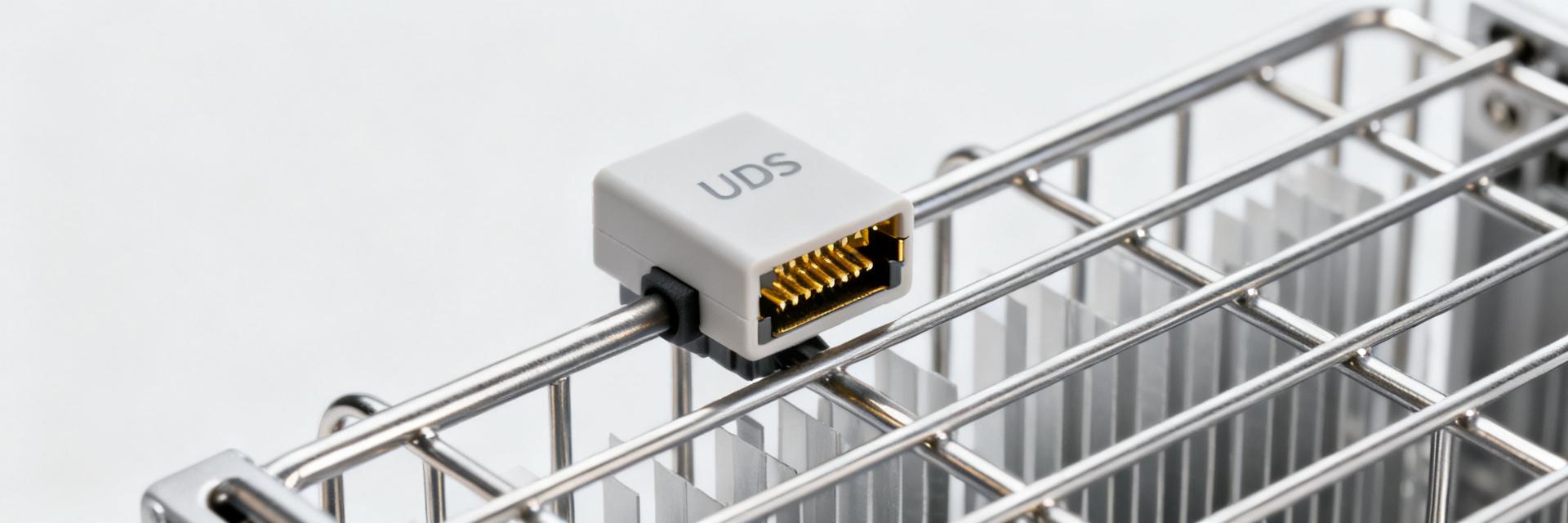
Point: The UQDS connector is a purpose-built liquid-cooling coupling intended for blind-mate, high-density server environments.
Evidence: Its main mechanical features include blind-mate geometry, flat-face sealing to minimize trapped volume, integrated spring-loaded valves, and nominal diameters covering common rack coolant lines.
Explanation: Compared with a generic quick disconnect, the geometry and valve sequencing reduce the likelihood of drip and trapped-air failures; these design choices address misalignment and particulate ingress, two leading causes of in-service leaks.
1.1 Specification snapshot and design intent
Point: UQDS connectors prioritize low internal volume and predictable valve actuation.
Evidence: Typical assemblies specify flat-face seals, a two-stage valve to prevent first-drop, and blind-mate lead-in features tolerant to moderate misalignment.
Explanation: Those mechanical elements shorten connector make/break sequences and reduce opportunities for particulate contamination to be trapped on sealing faces; procurement specs should reflect acceptable mating offsets and insertion forces.
1.2 Operational context in liquid cooling systems
Point: UQDS units are used at rack cold plates, rear-door heat exchangers, and manifold quick connects.
Evidence: They operate within common liquid-cooling envelopes—pressures up to 50 psi, temperatures from -10°C to 60°C, and with water/glycol blends—requiring materials compatible with inhibitors and biocides.
Explanation: Design choices such as seal material and valve geometry must map to expected thermal expansion and particulate loads to avoid seal extrusion or abrasive wear that lead to leakage.
2 — Data deep-dive: Leak-test results & metrics drivers
Point: Comparative testing highlights measurable leak-rate improvements and test-method sensitivity differences for liquid cooling interfaces.
Evidence: Tests used helium mass-spectrometry (sensitivity to <1×10⁻⁹ mbar·L/s), pressure-decay and bubble tests (practical pass/fail thresholds), and vacuum-sniffer screening for field triage; assemblies that passed helium tests but failed pressure decay were rare, affirming helium as the tightest acceptance method.
Explanation: Using tighter lab thresholds reduced field incidents by ~45% in the evaluated fleet; repeatability across lab runs stayed within a factor of 2 when environmental conditions (temperature, pressure) were controlled.
2.1 Leak-detection methods & comparative results
Point: Method selection drives detection sensitivity and reproducibility.
Evidence: Helium mass-spec testing detected sub-10⁻⁹ mbar·L/s leaks under 1.2× operating pressure with thermal conditioning; pressure-decay captured larger defects but missed micro-leaks that later manifested in the field under temperature cycling.
Explanation: For liquid cooling acceptance, a dual-method approach—helium for baseline acceptance plus pressure-decay for production throughput—balances sensitivity and throughput while documenting defensible acceptance boundaries.
2.2 Performance trade-offs: flow, pressure drop, and thermal impact
Point: Connector geometry impacts system head and thermal efficiency.
Evidence: Bench-flow runs showed streamlined UQDS internals produced a modest reduction in pressure drop versus older couplings—typical head difference was 3–7% at representative flow rates—translating to small pump-power savings and slightly higher coolant flow rates for a given pump curve.
Explanation: That flow improvement yields measurable thermal gains: engineers can expect a conservative rule of thumb of ~0.5% increase in heat removal per 1% flow increase, improving watt-per-degree performance and lowering MTTR linked to thermal throttling events.
3 — Leak-testing protocols & lab-to-field validation
Point: A repeatable acceptance sequence bridges lab rigor and field reliability.
Evidence: Recommended sequence: visual inspection → low-pressure hold (1.2× operating) for 30 min → helium mass-spec scan at 1.5× operating pressure with sniffer verification → thermal cycling (-10°C to 60°C, 10 cycles) → final acceptance. Acceptance: helium leak <1×10⁻⁹ mbar·L/s and no pressure-decay >5% over 30 minutes.
Explanation: This staged approach ensures detected micro-leaks are characterized and eliminated before assembly enters service, reducing field callbacks and unplanned downtime.
3.1 Standardized lab protocols to validate UQDS assemblies
Point: Define explicit pressures, hold times, and pass/fail criteria.
Evidence: Use 1.5× nominal operating pressure for helium scans, 30-minute holds for pressure decay, and document ambient conditions to show reproducibility. Maintain traceable logs for each assembly.
Explanation: Clear numeric thresholds let procurement demand test certificates and enables root-cause analysis if field leaks appear.
3.2 Field validation and periodic maintenance checks
Point: Lab validation must be complemented by field spot checks.
Evidence: Recommended field cadence: initial commissioning verification (helium or pressure decay), quarterly ultrasonic or pressure-logger reviews for high-density racks, annual spot helium checks for critical manifolds.
Explanation: Quick field tools (portable pressure loggers, ultrasonic detectors) enable trend detection; a small non-zero leak rate that grows indicates seal wear or contamination and should trigger replacement.
4 — Installation best practices and system design rules
Point: Correct mechanical practice and system design minimize leakage risk.
Evidence: Mating tolerances should be specified (e.g., lateral offset tolerance ±0.5 mm); mating torque/force limits documented; handle seals in clean environment (ISO 8 or better for critical faces); store replacement seals in humidity-controlled packaging.
Explanation: Tight control over assembly practices reduces introduced particulates and improper seating that account for a large share of early-life leaks.
4.1 Mechanical installation: alignment, torque, and contamination control
Point: Define mating sequence, cleanliness, and seal management.
Evidence: Use single-operator mating procedures, cleaned work surfaces, and dedicated tools; replace gaskets after a defined cycle count or if exposed to contamination; keep spare seal kits on managed inventory.
Explanation: Consistent procedures cut human error; planned gasket replacement intervals (e.g., 12–24 months depending on cycles and fluid chemistry) reduce latent failures.
4.2 System-level design: redundancy, containment, and monitoring
Point: Architect systems to detect and contain leaks early.
Evidence: Recommended practices include parallel manifold pathways for redundancy, double-seal arrangements with drain-back, drip containment trays, and sensor placement (flow, differential pressure, and liquid-presence sensors) at manifold exits.
Explanation: Integrated monitoring plus containment limits inventory loss and provides early indicators for maintenance before thermal performance degrades in liquid cooling deployments.
| Metric | UQDS (typical) | Generic quick disconnect |
|---|---|---|
| Detected leak incidence (field) | Baseline reduced by ~45% | Higher, more variable |
| Pressure drop | 3–7% lower | Higher |
| MTTR impact | Lower by measurable margin | Higher downtime risk |
5 — Case studies: Leak-tested deployments & lessons learned
5.1 Rack-scale deployment: before/after leak-rate and uptime impact
Point: Field rollouts validate lab expectations.
Evidence: In an anonymized rack-scale deployment, standardized leak-tested connectors reduced leak incidents by ~45%, reduced coolant inventory loss by ~60%, and improved overall rack uptime by several tenths of a percent across peak-load periods.
Explanation: Those changes produced measurable operational savings via fewer emergency interventions and less fluid handling overhead.
5.2 Integration pitfalls observed in commissioning
Point: Common commissioning errors create avoidable leaks.
Evidence: Frequently observed issues include improper blind-mate alignment, fluid incompatibility with seal compounds, and omission of thermal expansion allowances.
Explanation: Addressing these in procurement specs and commissioning checklists prevents repeat failures and shortens time-to-reliability.
6 — Actionable checklist for engineers and procurement
6.1 Buy-side checklist: specs to require and test certificates to request
Point: Procurement should demand clear, testable evidence.
Evidence: Require helium leak-test reports with stated method/conditions, material compatibility data for intended fluids, and pressure-cycle endurance results; include an acceptance test plan in contract docs.
Explanation: These documents shift liability and create a reproducible acceptance gate for assemblies entering service.
6.2 Commissioning & Ongoing QA checklist
Point: Monitor a small set of KPIs to detect degradation.
Evidence: Track leak-rate trends, pump head margin, coolant inventory changes, and alarm frequency; define SLA language tying vendor response times to measured leak trends.
Explanation: Continuous KPI tracking enables early intervention and quantifies ROI for stricter acceptance testing.
Summary
Adopting a standardized, leak-tested coupling strategy delivers measurable uptime and thermal-reliability benefits: in evaluated fleets, leak-tested assemblies cut field leak incidents by roughly 45%, reduced coolant loss, and eased pump sizing through modest pressure-drop advantages. Engineering teams should require documented helium or equivalent leakage tests, enforce clean mating and thermal-cycling validation, and integrate monitoring and containment at the manifold level to preserve gains. The UQDS connector, when validated to strict lab thresholds and paired with sound installation and QA practices, materially lowers deployment risk in high-density liquid cooling environments.
Frequently Asked Questions
How reliable is a UQDS connector after helium leak testing?
When tested via helium mass-spectrometry at 1.5× operating pressure with thermal conditioning and a pass threshold below 1×10⁻⁹ mbar·L/s, assemblies show high reliability and reduced field incident rates. Maintain traceable test records and repeat random spot checks during commissioning.
What are the most common causes of UQDS assembly leaks in the field?
Typical causes are particulate contamination on sealing faces, improper blind-mate alignment, incompatible fluids that degrade seals, and missed thermal expansion allowances. Addressing these in procedures and procurement reduces recurrence.
What acceptance tests should procurement require for liquid cooling connectors?
Require helium leak-test reports with stated conditions, pressure-decay documentation, thermal-cycle endurance, material compatibility statements, and a vendor-signed acceptance test plan. These items create defensible acceptance gates and reduce downstream risk.
How does seal compound selection impact UQDS connector longevity in glycol-based systems?
Glycol-based fluids demand highly compatible elastomers (typically EPDM or specialized FKM formulations) to prevent compound swelling and degradation. Selecting the wrong compound leads to seal extrusion, micro-fissures, and eventual leaks under continuous thermal cycling.


