





The AV87-15R4AZN is presented as a compact, circular multi-fiber solution intended for high-throughput, size‑constrained aerospace and defense systems. Point: it targets platforms where fiber-count density and ruggedization drive SWaP gains. Evidence: vendor-supplied qualification summaries and supplier data sheets report up to multi-hundred fiber assemblies in VITA-style circular shells. Explanation: consolidating many fibers into one interface reduces panel real estate and cable bulk while concentrating test and maintenance effort.
Point: this report gives engineers measurable evaluation items. Evidence: recommended spec fields and test matrices below are drawn from common qualification practice and supplier test-report norms. Explanation: use these to compare variants, validate optical/mechanical trade-offs, and to shape procurement language for turn-key cable assemblies.
1 — Background & Product Overview
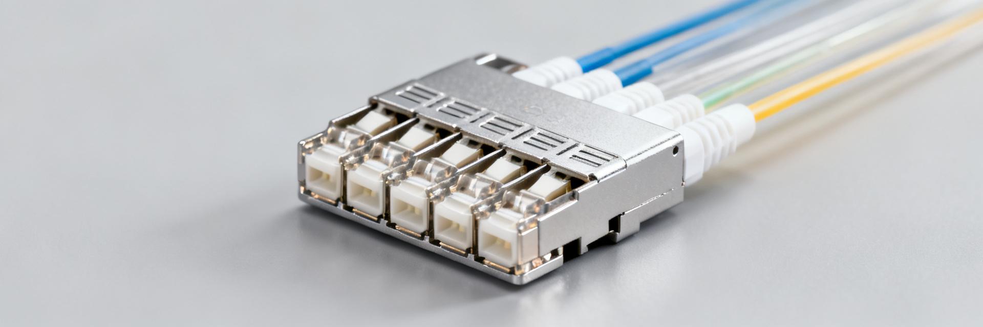
1.1 — Part-number decode & form factor
Point: the part code AV87-15R4AZN encodes family, shell series, insert style and feature suffixes. Evidence: typical decode maps family (AV87) → circular VITA-style shell, next digits → shell size/coupling, mid-suffix → ferrule/insert density, trailing letters → keying/sealing options. Explanation: confirming each field on a purchase order prevents mismatched ferrule type or sealing level and avoids rework when assemblies arrive.
| Configurable axis | Common options |
|---|---|
| Ferrule density | 8–48 fibers per MT ferrule; multi‑ferrule stacks to ~192 |
| Insert type | Fixed MT plate, removable cassette, or pigtail insert |
| Shell size | Circular shell series A–D (OD, panel cutout varies) |
| Coupling style | Threaded, bayonet, or captive coupling with gasket options |
1.2 — Typical applications & VITA 87 context
Point: target uses include airborne payloads, rugged backplanes, and SWaP‑sensitive communications racks. Evidence: industry application notes show widespread use in VITA 87 ecosystem installations where space and environmental robustness are critical. Explanation: designers measure success in bandwidth per cubic inch; high-density circular MT inserts deliver high fiber count in minimal envelope while meeting VITA 87 mechanical interfaces when specified correctly.
2 — Technical Specification Deep-Dive
2.1 — Mechanical & electrical/optical interfaces
Point: mechanical interface and ferrule choices determine mating behavior and panel requirements. Evidence: standard MT ferrules (precision molded MT arrays) and circular shells with locking coupling are typical; manufacturers publish nominal outer diameters and panel cutouts. Explanation: specify max shell OD, panel thickness clearances, torque or capture force ranges, and minimum mating cycles (e.g., 500–1,000 cycles vendor-specified) as "must-have" fields on the spec sheet for integration planning. The design here is a high-density MT connector optimized for dense fiber consolidation.
2.2 — Optical characteristics & materials
Point: optical performance depends on ferrule finish, alignment, and material stability. Evidence: baseline targets are commonly vendor-supplied IL ≤0.5 dB per mated ferrule pair and ORL >40 dB for single-mode polishing; ferrules use zirconia or precision polymer composites and insulators use low-outgassing plastics. Explanation: list expected IL and ORL, note temperature tolerances (vendor-supplied curves), and require material data (CTE, moisture uptake) to ensure optical stability across operational ranges.
3 — Performance Data & Validation
3.1 — Environmental and mechanical qualification
Point: acceptance criteria must reflect expected platform stresses. Evidence: typical test suites include thermal cycling, vibration (random and sine), mechanical shock, salt fog, humidity, IP sealing checks, and connector durability (mating cycles). Explanation: request supplier test reports showing pre/post IL/ORL with explicit thresholds (e.g., IL change ≤0.2 dB after thermal cycling, retention of mechanical latching, no ingress after salt fog) and include a simple test matrix on purchase orders.
| Test | Typical acceptance |
|---|---|
| Thermal cycling | ΔIL ≤0.2 dB; no mechanical failure |
| Vibration/shock | No discontinuity >1 μs; IL stability |
| Mating cycles | ≥500 cycles with IL drift within vendor tolerance |
3.2 — Optical test methods & example results
Point: standardized IL and ORL measurement practices improve comparability. Evidence: use calibrated test jumpers, specified wavelengths (e.g., 1310/1550 nm for SM), and pre/post clean protocols; vendors typically report averaged IL per ferrule and worst-channel metrics. Explanation: request measurement tolerances (±0.05 dB), temperature points for attenuation vs. temperature, and explicit cleaning/inspection photos or logs with test reports to flag IL drift >0.2 dB as a red flag.
4 — Use Case: System Integration Example
4.1 — Example: airborne communications payload integration
Point: integration requires variant selection, cable routing and environmental sealing. Evidence: a minimal BOM from field integrations includes connector variant, factory-terminated pigtail assembly, sealing kit and test adapters. Explanation: follow a panel-first mounting sequence, confirm bend radii and strain-relief locations, and order a sealed variant if exposed to external environments; list items below serve as a template.
- Sample BOM: AV87 shell variant (specify insert/ferrule), pigtail assembly (fiber type, length), sealing kit, test adapter set.
4.2 — Comparative analysis vs. alternative density approaches
Point: high-density MT designs trade repairability for size. Evidence: comparison studies show faster initial install but longer field service time when individual fibers fail compared with modular LC or duplex approaches. Explanation: choose high-density MT when bandwidth/volume and weight savings outweigh increased spare parts complexity; select modular lower-density interfaces where frequent field rework is expected.
5 — Procurement, Compliance & Maintenance Checklist
5.1 — Pre-procurement verification & ordering matrix
Point: clear ordering data prevents mismatches. Evidence: a pre-order checklist should capture full part number breakdown, ferrule/fiber count, polish type, keying, sealing options, and required supplier test reports. Explanation: explicitly reference VITA 87 compatibility and confirm the AV87-15R4AZN variant fields on purchase orders; flag long-lead items such as custom inserts and sealed mating rings.
5.2 — Maintenance, inspection & spare-parts planning
Point: planned spares and SOPs limit downtime. Evidence: inspection intervals typically align with mission cadence (quarterly for deployed airborne systems) and cleaning uses approved MT cleaning tools and lenses. Explanation: specify spare counts (e.g., one full spare insert per three systems plus 10% spare pigtails), acceptance criteria for re-install (visual cleanliness, IL within acceptance), and retest requirements after any field servicing.
Summary
Point: the AV87-15R4AZN family provides a compact path to very high fiber density in rugged platforms. Evidence: when specified with vendor test reports and clear procurement language, it meets VITA-style deployment needs. Explanation: focus evaluation on correct variant selection, verified optical/mechanical data, and practical integration and maintenance planning to realize SWaP and bandwidth objectives.
Key Summary
- Variant selection and full part-number verification are critical; specify ferrule type, polish, keying, and sealing to avoid mismatches and rework.
- Require vendor test reports showing IL, ORL, and environmental durability (thermal, vibration, mating cycles) with defined pass/fail thresholds for acceptance.
- Plan integration trade-offs: high-density MT gives bandwidth/size savings but increases repair complexity—balance spares and access accordingly.
Frequently Asked Questions
What fiber counts does a high-density MT connector support and how does that affect integration?
High-density MT connectors can consolidate tens to nearly two hundred fibers in a circular assembly depending on ferrule stacking and insert choice. Integration impacts include tighter bend-radius control, denser panel routing, and potentially longer repair times; plan cable management and spares to offset concentrated failure modes.
How should optical insertion loss be specified for a high-density MT connector system?
Specify typical per-ferrule IL targets (e.g., ≤0.5 dB typical) and maximum allowed IL drift after environmental tests (e.g., ≤0.2 dB). Require vendor test reports showing measurement methods, reference jumpers, wavelengths, and post-test results to enable apples‑to‑apples comparison.
How does a high-density MT connector change maintenance and spare‑parts planning?
Maintenance requires approved MT cleaning tools, visual inspection, and retest after any servicing. Spare strategy should include complete spare inserts and a selection of pigtails; recommend one full spare insert per three deployed units plus additional pigtails to minimize mission downtime.
What environmental and mechanical standards apply to the AV87-15R4AZN in aerospace payloads?
The connector is designed to comply with VITA 87 specifications, requiring qualification under MIL-STD-810G for thermal shock, random vibration (profile up to 46.3 Grms), and humidity. Specify post-test Delta-IL ≤0.2 dB to ensure physical and optical reliability.


