





The AV87-11R1ATN datasheet consolidates high-density MT connector specifications into a single technical reference for engineers and buyers. High-density MT families often deliver 8–24 fibers per ferrule with typical mated insertion loss in the 0.5–1.0 dB range under standard test conditions, making connector selection critical for system budget and rugged deployments. This article distills mechanical, optical, material, installation, and procurement guidance to accelerate specification checks and procurement decisions.
(1) Overview & standards — quick reference to AV87 specs
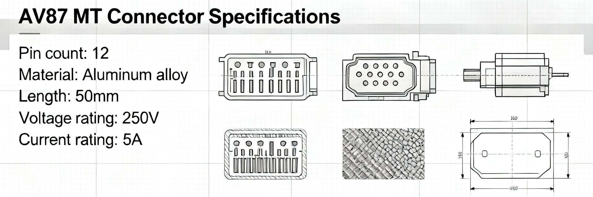
Point: Quickly locate the most used AV87 specs fields on the datasheet. Evidence: Part-number decoding, mechanical drawings, and test tables are primary. Explanation: For fast evaluation check mechanical dimensions first, then optical performance, followed by materials and environmental tables to confirm compatibility with the target application.
(1.1) What the AV87-11R1ATN is and how to read the part number
Point: The part number encodes family, size and configuration to speed ordering. Evidence: The AV87 family denotes a high-density MT form factor; size field (11) indicates shell size and contact density; suffixes indicate keying, receptacle or plug, and termination style. Explanation: Read the datasheet’s part-number breakdown and annotated drawing first to confirm shell, receptacle type, and insert arrangement before deeper spec checks.
(1.2) Applicable standards, ratings and compliance summary
Point: Expect mil-style and VITA-like qualification references and common tests. Evidence: Typical datasheets list shock, vibration, salt spray, temperature cycling, and mating-cycle ratings. Explanation: Build a simple three-column table in your review: standard → what it verifies → datasheet location to prioritize pass/fail checks during procurement and acceptance testing.
(2) Mechanical & dimensional specifications (data deep‑dive)
Point: Mechanical dimensions drive panel cutout, weight, and mating clearance decisions. Evidence: Datasheets provide shell size, thread type, panel cutout, and mating face dimensions. Explanation: Capture critical tolerances (±0.1 mm on mating face, mounting hole positions) and list them in a mechanical-dimensions table to prevent fit conflicts in chassis or bulkhead designs.
| Mechanical Parameter | Specification Limit / Tolerance | Compliance Standard Reference |
|---|---|---|
| Shell Size & Thread | Size 11, Class 2A Unified Threads | MIL-DTL-38999 Equivalent |
| Panel Cutout Diameter | Ø 19.5 mm ±0.1 mm | Standard Flange Mount Geometry |
| Mating Alignment | Precision Guide Pins (Ø 0.7 mm) | IEC 61754-5 (MT Interfaces) |
| Operating Temperature | -55°C to +125°C | EIA-364-1000 |
(2.1) Shell, mounting and interface dimensions
Point: Shell size and thread determine mounting hardware and panel preparation. Evidence: Size 11 shells typically specify thread class, panel thickness range, and flange or jam-nut details. Explanation: Report shell OD, panel cutout, and retention features with their tolerances; verify mating-face clearance and weight per connector for installed-mass budgets.
(2.2) Environmental and mechanical performance limits
Point: Environmental ratings determine suitability for airborne, vehicle, or industrial use. Evidence: Expect temperature ranges, IP or sealing class, shock/vibration levels, and mating-cycle counts. Explanation: Map these specs against system requirements—higher shock/vibe and broader temperature ranges are critical for avionics; confirm sealing and retention cycle counts for mobile ground vehicles.
(3) Optical & performance specifications (data deep‑dive)
Point: Optical performance defines link loss budget and channel capacity. Evidence: Datasheets list fiber count per ferrule, insertion loss, return loss, and test wavelengths. Explanation: Capture the typical vs. maximum insertion loss values and test conditions (e.g., single‑mode at 1310/1550 nm) to verify end-to-end budget and margin.
(3.1) Fiber count, ferrule type, insertion & return loss
Point: Fiber arrangement and ferrule technology drive density and loss. Evidence: High‑density MT ferrules commonly host 8–24 fibers; typical mated insertion loss is 0.5–1.0 dB and return loss ≥40 dB for standard polished ferrules under reference wavelengths. Explanation: Use a table: parameter → typical value → test condition (e.g., IL 0.6 dB → 1310/1550 nm) when comparing alternatives.
| Optical Parameter | Typical Performance | Worst-Case Limit | Wavelength / Test Band |
|---|---|---|---|
| Insertion Loss (IL) | 0.55 dB | 1.00 dB | 1310 nm / 1550 nm (SM) |
| Return Loss (RL) | ≥ 45 dB | ≥ 40 dB | Standard UPC Polish |
| Channel Capacity | 12 / 24 Fibers | 24 Fibers Max | Ribbon Fiber Configurations |
(3.2) Supported fiber types and wavelength/ bandwidth considerations
Point: Compatibility with single‑mode and multimode fibers affects throughput and wavelength planning. Evidence: Datasheets specify recommended fiber types and wavelength bands for measured loss. Explanation: Confirm whether the connector assumes single‑mode ferrules, multimode graded‑index, or mixed configurations; map fibers-per-connector to channel capacity and aggregate throughput for system planning.
(4) Materials, finishes & connector materials (materials & corrosion/thermal guidance)
Point: Material choices balance strength, EMI shielding, weight, and corrosion resistance. Evidence: Shells are often aluminum alloy, stainless, or composite with various finishes. Explanation: Review the materials table on the datasheet for shell alloy, insert material, and plating; record trade-offs between weight and corrosion protection for your environment.
(4.1) Shell, insert and structural material options
Point: Choose shell materials based on mechanical and EMI needs—this is part of AV87 specs evaluation. Evidence: Aluminum alloys reduce weight but require plating for corrosion; stainless offers durability and EMI but increases mass. Explanation: Note shell material, finish, and any EMI gaskets in the datasheet to ensure compliance with structural and electromagnetic requirements.
(4.2) Ferrule, seals, adhesives and plating details
Point: Ferrule and seal materials influence optical stability and sealing performance. Evidence: Ceramic ferrules give low attenuation and high repeatability; elastomer seals provide IP-rated protection; common platings include nickel for corrosion resistance. Explanation: Verify ferrule polish type, seal compound, and plating compatibility with adhesives and soldering processes in installation workflows.
(5) Installation, handling & test procedures (method guide for engineers)
Point: Proper assembly and torque practices preserve performance. Evidence: Datasheets often list recommended torque ranges, mating sequence and maximum retention loads. Explanation: Record torque values, strain‑relief methods, and recommended mating order; add a checklist for installers: verify part number, inspect ferrule faces, torque fasteners, and validate cable routing.
(5.1) Assembly, torque, mounting and cable management best practices
Point: Controlled installation minimizes mechanical stress and optical loss. Evidence: Typical torque ranges are small and must be applied with calibrated tools; strain relief prevents cable fatigue. Explanation: Use a mounting checklist: verify panel cutout, apply specified torque, secure strain relief, and avoid sharp bends within the first 50 mm of the connector interface.
(5.2) Cleaning, inspection and qualification testing
Point: Regular inspection and post-install testing confirm link integrity. Evidence: Common procedures include visual ferrule inspection, insertion‑loss testing, and environmental verification after installation. Explanation: Adopt pass/fail criteria for IL and RL, perform fiber‑end cleaning with approved solvents and tools, and log test results for configuration control and warranty evidence.
(6) Use cases, procurement checklist & cross-reference tips (actionable)
Point: Match connector features to application-specific priorities to avoid costly rework. Evidence: Applications like rugged avionics prioritize weight and wide temperature range; industrial comms emphasize sealing and high mating cycles. Explanation: Create short spec-match scenarios to map primary required attributes—mechanical tolerances, optical loss, materials—against candidate parts during procurement.
(6.1) Typical applications and quick spec-match scenarios
Point: Example scenarios speed decision-making. Evidence: Rugged avionics require weight‑conscious shells and broad temperature range; ground vehicles favor robust sealing and vibration tolerance; datacom emphasizes low insertion loss and high fiber count. Explanation: For each use case, list three must-have specs to verify first: mechanical fit, optical IL/RL, and material/finish suitability.
(6.2) Datasheet buying checklist & alternate-part considerations
Point: A procurement checklist reduces mismatched orders. Evidence: Confirm full part number, shell material and finish, termination style, IL/RL class, mating cycles, and required certifications. Explanation: Request dimensional drawings, material callouts, test reports and lead time estimates; when cross-referencing, prioritize environmental rating and optical grade over cosmetic finish differences.
Summary
- Verify mechanical fit first: confirm shell size, panel cutout and mating-face tolerances against the AV87-11R1ATN datasheet to avoid integration rework; record critical tolerances and mounting torque values.
- Confirm optical budget: capture fiber count per ferrule, typical and maximum insertion loss, and test wavelengths to ensure system margin; use standardized IL/RL test conditions for apples-to-apples comparison.
- Assess connector materials: review shell alloy, plating and ferrule material—connector materials choices affect corrosion resistance, weight and EMI performance and must match operational environment.
- Follow installation and test discipline: use specified torque, strain relief, cleaning, and post-install IL verification to maintain performance and produce an auditable test record consistent with procurement requirements.
(Common Questions)
What does the AV87-11R1ATN datasheet specify about insertion loss?
Typical datasheet entries list both typical and maximum mated insertion loss values along with test wavelengths and conditions. Expect typical IL figures around 0.5–1.0 dB per mated junction under reference conditions; use the maximum value when budgeting worst-case link margin and plan connectors and splices accordingly.
How to interpret AV87-11R1ATN mechanical tolerances for panel integration?
Mechanical tables show panel cutout, mounting hole pattern and mating-face tolerances. Treat listed tolerances as functional limits: apply specified ± values to CAD cutouts, confirm thread class and panel thickness range, and validate with a mechanical prototype before volume production to prevent misfits.
What installation tests should follow using the AV87-11R1ATN datasheet guidance?
Post-install tests should include visual ferrule inspection, insertion-loss and return-loss verification at specified wavelengths, and environmental checks where applicable. Record results against datasheet pass/fail criteria, and repeat tests after environmental cycling if the application demands rugged qualification.
What material configurations optimize the AV87-11R1ATN for harsh environments?
To withstand extreme environments, specify aluminum alloy shells with electroless nickel or cadmium plating for superior corrosion resistance and EMI shielding. Combine this with fluorosilicone elastomer seals and high-precision ceramic or polyphenylene sulfide (PPS) MT ferrules to maintain optical alignment under extreme temperature cycling (-55°C to +125°C).


