





The AV87-11R1AZN is a high-density, rugged multi-fiber circular connector family notable for supporting MT ferrule assemblies with up to 48 fiber positions in compact envelopes used across military, aerospace, and high-reliability communications. This single-source technical reference consolidates mechanical drawings, pinout guidance, technical specs, environmental ratings, test procedures, and practical installation and troubleshooting guidance for system and procurement engineers.
Background & Product Overview
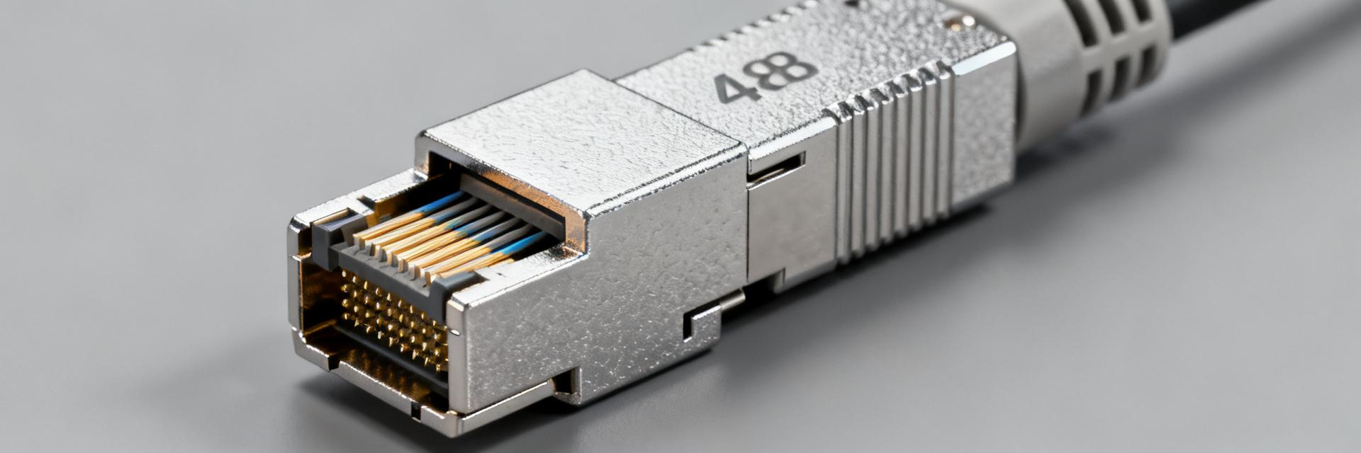
What the AV87-11R1AZN is (form factor & intended applications)
Point: The AV87-11R1AZN is a circular, high-density fiber optic connector intended for rugged system roles. Evidence: Typical deployments include backplanes, panel bulkheads, and cable-to-equipment interfaces in harsh environments. Explanation: Designers will find a compact, keyed form factor that balances high fiber count with mechanical robustness suitable for vibration, shock, and sealed enclosures.
Key differentiators & common variants
Point: Distinguishing features include MT ferrule compatibility and multiple density options. Evidence: Variants commonly differ by receptacle vs. plug, fiber count, and endface polish. Explanation: Engineers should verify variant suffixes to confirm mating type, fiber count, and polish (PC/UPC/APC) when specifying assemblies; common variants support different flange and bulkhead mounting options.
Complete Technical Specs (tab-ready detail)
Electrical & optical parameters
Point: Optical performance drives connector selection in link budgets. Evidence: Typical insertion loss per mated MT ferrule is 0.35 dB typical, 0.75 dB max; return loss commonly ≥ 35 dB for polished ferrules under standard test conditions. Explanation: Measurements assume singlemode testing wavelengths (1310 nm and 1550 nm) or multimode 850/1300 nm where applicable; verify test wavelength and reference plane in procurement.
| Parameter | Typical | Maximum / Notes |
|---|---|---|
| Insertion loss (per mated MT ferrule) | 0.35 dB | 0.75 dB (endface, alignment dependent) |
| Return loss | >35 dB (UPC) | >55 dB (APC, if applicable) |
| Fiber positions | Up to 48 | Dependent on ferrule density |
| Fiber types supported | SMF / MMF | Specify mode field diameter or OM-class |
| Optical power handling | Typical telecom levels | Verify for high-power laser use |
| Test conditions | Wavelengths: 850/1310/1550 nm | Refer to measurement reference plane and launch conditions |
Environmental & qualification ratings
Point: Deployment environments dictate qualification requirements. Evidence: Typical ratings include operating temperatures from -55°C to +125°C, shock to several hundred g, and broad vibration spectra. Explanation: Specify required IP or sealing level, altitude/pressure tolerances, and shock/vibration acceptance during procurement to ensure assemblies meet system-level reliability needs in severe environments.
Pinout & Signal Mapping
Pinout diagram & labeling
Point: Clear pin mapping is essential for assembly and test. Evidence: A labeled pinout diagram should present fiber position numbering, mating orientation, and keying. Explanation: Provide a high-resolution programmatic diagram with filename conventions such as "av87-11r1-pinout.svg" and descriptive alt text containing the term "pinout" to support documentation and CAD libraries for wiring and test teams.
Wiring, color codes & connector mating guidance
Point: Consistent wiring order and polarization reduce assembly errors. Evidence: Recommended practice sequences fibers per MT standard color code and define plug-to-receptacle orientation in documentation. Explanation: Include dos and don'ts: do confirm key orientation before mating, do use specified torque for panel fasteners, don't force mate under load; include close-up photos for critical mating faces during procedures.
Mechanical Dimensions & Mounting
Dimension drawings & critical tolerances
Point: Accurate dimensions are critical for PCB and panel integration. Evidence: Dimensioned drawings should list overall length, flange footprint, panel cutout, and mating depth with tolerances. Explanation: Highlight critical tolerances for board-to-socket alignment and panel recess; recommend designers source CAD models in STEP and native formats using clear naming conventions to avoid integration errors.
Mounting options, PCB footprint & hardware
Point: Mounting choices affect mechanical stability and EMI handling. Evidence: Common options include flange, threaded bulkhead, and PCB-mount adaptors with specified screw sizes and torque. Explanation: Provide recommended screw sizes, standoff heights, land pattern keepouts, and recommended clearance regions on the PCB; note that captive hardware reduces installation variability in production.
Performance Testing & Common Failure Modes
Recommended test procedures & pass/fail criteria
Point: Standardized tests verify assembly integrity. Evidence: Acceptance tests include insertion loss and return loss measurements, visual endface inspection, and environmental cycling to acceptance thresholds. Explanation: Define pass/fail numeric thresholds for each test, specify test equipment and reference jumpers, and document test setup photos or diagrams so manufacturing and QA can reproduce results consistently.
Troubleshooting checklist & repair/maintenance tips
Point: Most field issues arise from contamination or misalignment. Evidence: Troubleshooting steps should isolate fiber path, inspect ferrule endfaces, and verify mechanical mating. Explanation: Provide a stepwise flow: clean and inspect endfaces, verify keying and alignment, check torque and panel seating; replace ferrules for persistent losses beyond cleaning limits and document rework actions.
Typical Use Cases, Interoperability & Procurement Notes
Typical system integrations & compatibility tips
Point: Integration scenarios guide compatibility checks. Evidence: Common uses include high-density patching, backplane interfaces, and rugged cable assemblies using MT ferrules and adapters. Explanation: When integrating, confirm adapter ferrule alignment, cable bend radii, and endface polish type to ensure interoperability between panels, adapters, and cable assemblies in the target system.
Sourcing & part-number considerations (what to confirm when ordering)
Point: Accurate part interpretation avoids procurement mistakes. Evidence: Verify suffix meanings for mating type, fiber count, polish, and packaging options. Explanation: Request datasheet confirmation of technical specs, confirm polish and ferrule style (PC/UPC/APC where applicable), and specify acceptance test reports with deliveries to align supplier output with system requirements.
Summary (actionable takeaway)
- AV87-11R1AZN is a compact, rugged high-density connector optimized for MT ferrule assemblies and high-reliability environments; confirm fiber count and polish when designing and procuring.
- Validate technical specs through insertion-loss and return-loss testing at intended wavelengths and specify test setups and pass/fail criteria in procurement documents.
- Follow defined pinout and wiring documentation, use keyed mating orientation, and adhere to torque and mounting tolerances to prevent mechanical and optical failures.
- During sourcing, request CAD models, dimension drawings, and factory test reports; run prototype insertion-loss testing and verify footprint before production release.
FAQ & Diagnostic Details
What are the key technical specs for AV87-11R1AZN?
Key technical specs include typical insertion loss around 0.35 dB per mated MT ferrule and a maximum allowance near 0.75 dB, return loss suitable for UPC/APC variants, support for up to 48 fibers in MT ferrules, and operating temperatures commonly spanning -55°C to +125°C. Confirm wavelength and test reference plane during acceptance testing.
How should the pinout be documented for production?
Provide a clear pinout diagram showing fiber numbering, keying orientation, and mating direction. Name image files consistently, include alt text containing "pinout", and pair diagrams with a table mapping pin numbers to fiber positions and color codes so assembly and test teams can reproduce wiring reliably.
What tests should be run before deployment?
Run insertion loss, return loss, visual endface inspection, continuity checks, and environmental cycling representative of expected service conditions. Define numeric pass/fail thresholds in procurement, use calibrated test equipment, and retain test records for traceability; slight rework may follow cleaning, but replacements are recommended when alignment issues persist.
What are the primary failure modes and maintenance steps?
Most field failures stem from optical endface contamination or mechanical misalignment. Standard maintenance requires visual inspection using an endface microscope, dry or wet-to-dry cleaning using approved MT ferrule cleaners, and checking mechanical seating torque. If losses persist, inspect for physical fiber breaks or microbends near the connector boot.


