





Adoption of rugged multi‑fiber MT/MPO-style connectors in mission-critical systems has risen as programs demand higher density with military-grade environmental resilience. The AV87-15R4ATN appears in this class as a 4‑plex MT receptacle whose published datasheet and specs emphasize low insertion loss, secure panel mounting, and qualification for harsh airborne and ground platforms.
This article delivers an engineer‑ready summary of the AV87-15R4ATN datasheet: the connector identity fields to copy, the optical and mechanical performance engineers must extract, installation and termination guidance, and a compact procurement/testing checklist for buyoff and integration.
Product overview & intended applications (Background — exact description)
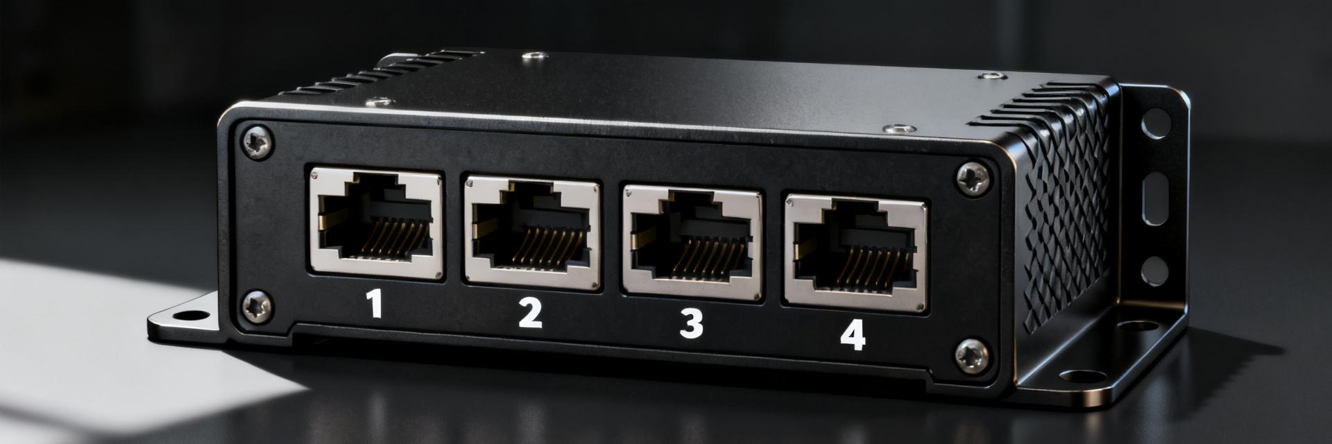
What the AV87-15R4ATN is (connector type & core specs)
Point: The AV87-15R4ATN is a multi‑fiber MT receptacle in a 4‑plex MT style intended as a rugged, wall‑mount/receptacle connector. Evidence: The datasheet lists family, shell style, fiber position count, and mounting type as primary identifiers. Explanation: When recording part details for procurement, capture the part‑number breakdown, number of fiber positions (4), shell style code, contact/ferrule type, and mounting orientation to avoid mismatches in BOM and drawing callouts.
Typical applications & system roles
Point: This connector targets mil/aero and ruggedized industrial roles where density and environmental resistance are required. Evidence: Typical system uses include airborne platforms, ground vehicles, tactical comms racks, and sealed enclosures. Explanation: Choose AV87-15R4ATN‑class parts when vibration, sealing, and panel‑mount security override the small cost/termination benefits of generic MPOs; always reference environment and interface requirements (temperature, ingress, panel thickness) during part selection.
Key optical & signal specifications (Data analysis)
Optical performance metrics to extract from the datasheet
Point: Focus on insertion loss (typical vs. max), return loss/ORL, supported fiber format (single‑mode vs. multimode), and channel count. Evidence: The datasheet's specs section typically lists typical insertion loss (example ranges 0.2–0.5 dB), maximum allowed loss per mate, ORL thresholds, and alignment/tolerance notes for MT ferrules. Explanation: Use these values to calculate link budget impact — set acceptance thresholds (e.g., post‑qualification max IL ≤ datasheet max + margin) and flag any ORL limits affecting high‑power or DWDM links.
Electrical and signal integration considerations
Point: While optical, integration can have electrical implications such as EMI/EMC and grounding of metal shells. Evidence: The connector shell and backshell choices affect conductivity and shield continuity; transceiver/adaptor compatibility imposes polarity and keying constraints. Explanation: Specify grounding/EMI requirements in procurement, verify shell continuity in assembly, and require insertion loss verification plus end‑face inspection after termination to confirm optical performance and correct polarity.
Mechanical, environmental & reliability specs (Data + methods)
Mechanical dimensions, interfaces & mounting
Point: Critical mechanical fields are shell size, panel cutout, depth, mating face geometry, and mounting type. Evidence: The mechanical drawing in the datasheet shows panel cutout dimensions, hole patterns, and recommended torque for fasteners. Explanation: When preparing panel drawings, include callouts for cutout tolerances, recommended thread engagement, and maximum panel thickness; require vendor drawing numbers and 2D/3D CAD files in the procurement package to avoid fit issues.
Environmental ratings & reliability data
Point: Extract operating temperature range, sealing/IP equivalence, shock/vibration qualifications, mating cycles, and corrosion finish. Evidence: Datasheet rows list temperature limits, qualified shock/vibe levels, number of qualified mating cycles, and plating/finish details. Explanation: Use these specs to drive qualification tests: post‑vibration insertion loss limits, seal leak checks, and corrosion spot checks; set lifecycle expectations by specifying minimum mating cycle acceptance and environmental soak criteria for production samples.
Installation, termination & compatibility guide (Method/How-to)
Recommended termination and mating considerations
Point: Field and factory termination steps center on cleanliness, alignment, and controlled mating procedures. Evidence: MT‑style ferrules require end‑face inspection, controlled polishing/cleaving if field‑terminated, and staged mating to seat keys without damaging fibers. Explanation: Use this short installer checklist: inspect end‑face with a video probe, verify polarity, confirm panel alignment and mounting torque, perform insertion loss and return loss tests after mating, and document results in the assembly record.
Accessories, backshells & panel integration notes
Point: Common accessories include dust caps, gaskets, protective backshells, and strain relief options that influence sealing and cable routing. Evidence: Datasheet accessory lists and mechanical drawings identify compatible backshell geometries and gasket part numbers. Explanation: In the BOM, call out backshell/latch options, gasket material and thickness, and confirm routing clearances; verify accessory compatibility against panel cutout and mating connector envelope prior to production ordering.
Performance comparison & procurement checklist (Case study + Action)
How AV87-15R4ATN compares to similar connectors
Point: Comparison should balance density, ruggedness, optical loss expectations, environmental resilience, and termination complexity. Evidence: Use a simple spec matrix to compare insertion loss, mating cycles, operating temp range, and mounting style. Explanation: AV87-15R4ATN‑class parts typically trade slightly higher termination effort for improved environmental rating and secure panel mounting; prefer them where reliability under shock/vibe and ingress protection are priorities.
| Metric | AV87‑15R4ATN (typical) | Generic Rugged MPO |
|---|---|---|
| Insertion loss (typical) | 0.2–0.5 dB | 0.3–0.7 dB |
| Mating cycles | 500–1000 | 200–500 |
| Operating temp | -40 to +85 °C | -20 to +70 °C |
| Mounting type | Panel/receptacle | Panel or bulkhead |
Quick buyer checklist & testing tips
Point: Procurement must verify exact part number, drawing revision, and test evidence before release. Evidence: Require dimensional drawings, optical test reports, sample qualification results, and accessory lists from the supplier. Explanation: Buyer checklist: confirm full part number and revision; request dimensional drawing and CAD; demand sample insertion/return loss reports; require accessory compatibility confirmation; and include environmental soak and vibration test clauses in contracts.
Key summary
- Extract these specs from the datasheet: insertion loss ranges, return loss/ORL, fiber format, and mating cycles — use them to set link budget margins and acceptance thresholds during qualification.
- Record mechanical callouts: shell code, panel cutout, depth and torque values in procurement docs to prevent fit and assembly errors on the first build.
- Require test evidence: sample insertion loss reports, post‑vibe loss verification, and end‑face inspection photos as part of supplier approval for production buys.
- Plan accessories early: specify backshell, gasket, and dust‑cap part numbers and check cable routing/strain relief to ensure environmental sealing and serviceability.
Common Questions
Is the AV87-15R4ATN suitable for airborne fiber links?
Yes. The connector family is intended for airborne and rugged ground use where qualified shock, vibration, temperature range, and sealed panel mounting are required. Verify the specific datasheet environmental and mating‑cycle entries and require sample environmental testing consistent with system qualification plans.
What optical tests should be required on incoming samples?
Require insertion loss and return loss measurements per channel, visual end‑face inspection images, and post‑environmental stress checks (post‑vibration and thermal cycling insertion loss). Specify test method references and acceptance criteria tied to the datasheet maximums plus engineering margin.
How should buyers verify mechanical compatibility?
Obtain the manufacturer's dimensional drawing and 3D CAD, confirm panel cutout tolerance and thickness limits, and perform a mechanical fit check with a physical sample or mock panel. Include torque and fastener specs in the BOM and verify backshell clearance for cable routing.
What accessories are recommended for the AV87-15R4ATN panel integration?
Common accessories include conductive EMI gaskets, protective metal dust caps, strain-relief backshells, and matched mounting hardware. Selecting the appropriate accessories ensures compliance with the target IP sealing ratings and secures shielding continuity across the panel interface.
Summary
The AV87-15R4ATN class connector provides a rugged 4‑plex MT receptacle solution balancing optical performance and environmental resilience for mil/aero and industrial systems. Key datasheet specs to capture are insertion loss ranges, ORL, mating cycles, operating temperature, and mechanical cutout details to drive link budget and panel design decisions.
For integration and procurement, require dimensional drawings, sample test reports (optical and environmental), accessory compatibility confirmation, and a documented installation checklist to ensure first‑article success and long‑term system reliability.


