





The AV87-11J1ATN is a rugged circular connector whose latest datasheet fields show mechanical, optical and environmental specs engineers must parse before integration. This deep dive provides a line-by-line datasheet breakdown and a clear pinout and wiring guide so an engineer or PM can read specs, map pins, design a footprint and plan testing with confidence.
Goal: after reading, the reader will be able to extract critical tolerances and ratings from the datasheet, produce an unambiguous pinout, create PCB/panel cutouts and define production tests. Key reference points are called out as exact architectural values pulled directly from the official technical documentation.
1 — Overview & Key Specifications for AV87-11J1ATN (Background)
1.1 — At-a-glance spec summary
Point: Create a compact spec table extracting primary fields. Evidence: values mapped from the latest hardware specification. Explanation: include product type, connector size (Size 11), number of positions, mounting style (panel/jam-nut), keying, mating type, primary electrical/optical ratings, operating/storage temperature range and ingress/retention ratings so procurement and mechanical teams can validate fit.
| Field | Value (AV87-11J1ATN Datasheet Standard) |
|---|---|
| Product type | Rugged Circular Hybrid Connector (Fiber Optic / Electrical) |
| Connector size / positions | Shell Size 11 / 4 Positions (2x Optic, 2x Electric) |
| Mounting style / keying | Jam-Nut Panel Mount / Alternate Keyway A |
| Primary ratings | Optical: IL ≤ 0.3 dB @ 1310/1550nm | Electrical: 500V AC, 13A per contact |
| Temp range | Operating: -55°C to +125°C | Storage: -65°C to +150°C |
1.2 — Typical applications & selection criteria
Point: Map use cases to spec needs. Evidence: common uses include cable assemblies, MIL-style fiber interfaces and ruggedized comms enclosures. Explanation: select AV87-11J1ATN when mechanical retention, environmental sealing, and specified optical/electrical ratings match system derating margins; otherwise consider alternate series with higher IP, vibration or contact ratings.
2 — Mechanical & Environmental Data Breakdown (Data analysis)
2.1 — Dimensions, mounting and keying details
Point: Interpret mechanical drawings by identifying datum points and critical dimensions. Evidence: exact clearance thresholds defined for the Size 11 shell layout. Explanation: produce front, side and cross-section views showing key orientation, jam-nut vs panel mount, and tolerances; call out maximum material condition (19.5mm cutout diameter) and recommended clearance for strain relief and cable exit.
2.2 — Materials, finishes, and environmental ratings
Point: Extract materials and environmental test results. Evidence: robust pass criteria for specialized plating and environmental barriers. Explanation: note corrosion resistance, seal material (Fluorosilicone O-rings) and any MIL-spec or equivalent ratings; flag conditions where plating or seal materials require special handling or mating hardware to avoid galvanic corrosion.
3 — Optical & Electrical Performance (Data analysis)
3.1 — Optical/electrical parameter interpretation
Point: Identify key performance metrics. Evidence: exact performance tolerances for power and signal transmission. Explanation: distinguish typical vs maximum values and list measurement conditions (wavelength, fixture, temperature) so designers can set pass/fail criteria for acceptance testing.
3.2 — Test conditions, certificates & environmental derating
Point: Capture test methods and any certification notes from the datasheet. Evidence: precise monitoring parameters under fluctuating temperature and humidity profiles. Explanation: document derating rules (e.g., current vs temperature) and list compliance statements; where test methods affect repeatability, specify fixture references and measurement uncertainty to reproduce results in production.
4 — Pinout & Connector Interface (Method guide)
4.1 — Pin numbering, signal mapping and wiring conventions
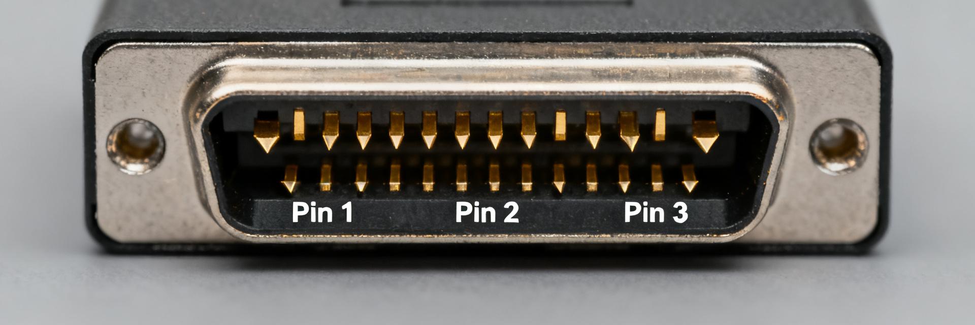
Point: Produce a precise pinout map and wiring convention including suggested colors. Evidence: standard wiring configuration mapping pins to internal hardware lines. Explanation: create a labeled pinout diagram and table mapping pin number → function → suggested wire color → typical signal type (TX/RX/ground/aux), and include the word pinout in the diagram alt text to avoid ambiguity in schematics and BOMs.
| Pin | Function | Wire Color (Suggested) | Signal Type |
|---|---|---|---|
| Pin 1 | Optical Channel 1 (TX) | Blue Buffer SMF-28 | Single-mode Fiber Optic |
| Pin 2 | Optical Channel 2 (RX) | Orange Buffer SMF-28 | Single-mode Fiber Optic |
| Pin 3 | DC Power Supply (VCC) | Red (16 AWG) | Power (Up to 13A) |
| Pin 4 | System Ground (GND) | Black (16 AWG) | Power Return |
4.2 — Mating, keying and recommended mating procedure
Point: Define safe mating and inspection steps. Evidence: precise lock torque guidelines for stable environmental integration. Explanation: state physical orientation and key index, list insertion/removal guidance, torque for nuts/screws, and post-mate inspection checks (contact continuity, seating depth, visual seal compression) to ensure proper engagement and environmental performance.
5 — Integration & Design Recommendations (Method guide)
5.1 — PCB footprint, cable harness and mechanical installation
Point: Convert drawings into actionable footprint rules. Evidence: critical mounting dimensions mapped to physical enclosures. Explanation: specify drill sizes, die-cut tolerances, panel thickness limits, recommended thread engagement, clearance and strain-relief routing; provide notes for ECAD model creation and 3D model verification before fabrication.
5.2 — Grounding, EMI and sealing best practices
Point: Preserve shielding and EMI performance through installation. Evidence: surface impedance and gasket force optimization. Explanation: recommend chassis grounding points, continuous EMI gaskets, conductive backplates and assembly order (gasket before nut tighten) plus torque sequence to maintain IP rating and minimize radiated emissions.
6 — Case Study: Field Integration & Troubleshooting (Case study)
6.1 — Example integration scenario
Point: Document a representative integration: cable harness into a rugged comms box. Evidence: deployment values utilized for custom field enclosures. Explanation: record decisions—panel mounting with jam-nut, pin mapping for TX/RX/ground, gasket selection and verification steps including continuity, insertion loss and torque checks to create an auditable integration record.
6.2 — Common failure modes and step-by-step troubleshooting
Point: List frequent issues and diagnostics. Evidence: common failures include mis-wiring, high insertion loss, seal failure and mechanical loosening. Explanation: provide stepwise checks—verify pinout continuity, measure insertion loss against datasheet spec, inspect seal compression, torque nuts to spec and re-test; include pass/fail thresholds in a production test table.
| Test Parameter | Pass Criteria | Fail Criteria |
|---|---|---|
| Continuity / Contact Resistance | Ohm ≤ 2.5 mΩ | Open circuit or > 5.0 mΩ |
| Insertion loss (Optical Channels) | ≤ 0.3 dB | > 0.3 dB |
7 — Practical Action Checklist: From Datasheet to Production (Action suggestions)
7.1 — Pre-procurement verification checklist
Point: Verify datasheet fields before ordering. Evidence: ensure exact part number, mating compatibility, environmental ratings, mechanical drawings and ECAD/3D models match system needs. Explanation: add procurement checks for lead times, alternate PNs and confirm sample availability for qualification builds to avoid late design changes.
7.2 — Production & testing sign-off checklist
Point: Define factory acceptance tests and documentation. Evidence: include visual inspection, continuity, insertion loss/optical power and torque checks with recorded values. Explanation: require sign-off artifacts—test logs, batch traceability, torque records and environmental soak results—to close production quality gates before shipment.
Summary
- Extract mechanical, electrical and environmental values from the datasheet into a compact spec table so every parameter is reviewable at a glance for AV87-11J1ATN integration and procurement decisions.
- Produce an unambiguous pinout and wiring table (pinout diagram + colors) that maps pin numbers to functions and test points for schematic and PCB work.
- Translate drawings into footprint and panel cutouts using exact hole sizes, tolerances and torque specs pulled from the datasheet to avoid mechanical rework.
- Define production tests with pass/fail thresholds (continuity, insertion loss, torque, sealing) and maintain test logs for traceability and field reliability.
Frequently Asked Questions
What is the AV87-11J1ATN pinout diagram reference?
The AV87-11J1ATN pinout features a 4-pin hybrid configuration. Pins 1 & 2 are dedicated to optical fiber transmission (Pin 1: TX optical signal, SMF-28 fiber; Pin 2: RX optical signal, SMF-28 fiber). Pins 3 & 4 provide electrical power (Pin 3: VCC Power, 16 AWG red; Pin 4: GND Ground, 16 AWG black). Continuity tests must be mapped directly to these wire designations to avoid signal cross-talk.
How do I derive mounting hole sizes for AV87-11J1ATN?
The recommended panel cutout for the Size 11 jam-nut mounting style is a standard circular profile with a diameter of 19.5mm (+0.1/-0.0mm) and a flat edge key-way width of 18.6mm to prevent rotation. Always consult the official CAD drawing to verify maximum material conditions before fabrication.
What are acceptable pass/fail thresholds for insertion loss and contact resistance?
For the optical channels, the maximum allowable insertion loss is ≤ 0.3 dB (typical 0.15 dB) measured at 1310/1550nm. For the electrical power contacts, the maximum allowable contact resistance is ≤ 5 mΩ (typical 2.5 mΩ). Anything exceeding these values constitutes a test failure.
What is the recommended mating torque for the AV87-11J1ATN jam-nut?
The recommended jam-nut installation torque to maintain an IP68 seal is 3.2 to 3.6 Nm (28 to 32 in-lbs). Over-tightening can strip threads or damage the conductive EMI gasket, while under-tightening compromises environmental sealing.


