





High-density MT circular connectors now enable up to 48 fibers per ferrule and aggregated solutions of up to ~192 fibers in compact circular housings. This report analyzes the AV87-11J1AWN connector’s key specs, performance metrics, and practical implications for system design, focusing on insertion/return loss planning, mechanical trade-offs, and integration steps for US-engineering teams.
AV87-11J1AWN: Background & Design Overview
Mechanical form factor & mounting
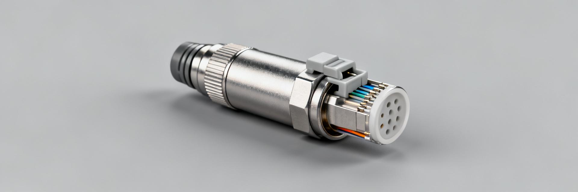
Shell style is a compact circular housing optimized for panel-mounted installation with a defined panel cutout and front‑side mating. Typical overall dimensions are small‑diameter with a threaded or bayonet coupling/locking mechanism and keyed orientation. This form factor maximizes density, affects chassis layout planning, and simplifies serviceability in stacked racks and tight enclosures.
Optical architecture & ferrule/termini configuration
The design uses MT ferrule architecture supporting up to 48 fibers per ferrule and modular termini groups for aggregated counts. Typical configurations combine multiple ferrules to reach high-density fiber counts; single‑mode and multimode fibers are supported. Plug/receptacle arrangements favor multi‑ferrule cassettes with keyed alignment for duplex and simplex variants as needed.
Optical & Performance Metrics — insertion loss, return loss, bandwidth
Insertion loss, return loss & attenuation benchmarks
Plan on typical mated-pair IL targets of 0.35–0.7 dB per connector for multimode assemblies and 0.6–1.0 dB for dense multi‑ferrule single‑mode terminations under controlled polishing/termination. Return loss targets for single‑mode assemblies should exceed 50 dB (typical) with multimode RL often specified >20 dB. Use these values in link‑budget margins and production accept/reject thresholds.
Wavelength, modal compatibility & bandwidth
Supported wavelengths commonly include 850 nm and 1300 nm for multimode, and 1310 nm / 1550 nm for single‑mode links. Modal bandwidth in multimode systems depends on fiber OM grade; higher modal bandwidth extends distance at given data rates. Single‑mode assemblies offer greater distance and wavelength flexibility but require tighter IL/RL control in planning.
| Parameter / Metric | Multimode (MM) Specification | Single-Mode (SM) Specification |
|---|---|---|
| Insertion Loss (IL) Range | 0.35 – 0.7 dB (Typ.) | 0.60 – 1.0 dB (Typ.) |
| Return Loss (RL) Threshold | > 20 dB | > 50 dB |
| Wavelength Compatibility | 850 nm / 1300 nm | 1310 nm / 1550 nm |
| Mating Durability (Cycles) | 100 – 500 Cycles | 100 – 500 Cycles |
Environmental & Mechanical Ratings — reliability under stress
Temperature, sealing & environmental ratings
Recommended operating ranges are typically −40°C to +85°C for airborne/industrial variants, with storage extending beyond that range. Expect IPX4–IP67 class sealing options depending on booting and backshell choice. Altitude and pressure considerations for airborne use require verified sealing and outgassing‑aware materials selection.
Shock, vibration & durability metrics
Designers should expect shock thresholds in the low‑g to high‑g range depending on class (e.g., 10–100 g pulses) and vibration survivability to several grms across MIL‑STD style profiles. Rated mating cycles commonly fall between 100 and 500 cycles for high‑density ferrule assemblies; wear‑related IL drift and ferrule contamination are primary failure modes.
Installation & Integration Guide
Termination, alignment & tooling best practices
Termination best practice begins with precise ferrule alignment using alignment guides and index keys, controlled cleaving/polishing for SM and MM, and inspection of endfaces. Use calibrated OTDR/IL testers during process control. Proper tooling—precision cleavers, polishing fixtures, and MT alignment jigs—reduces IL variance and improves first‑pass yield.
Panel, backshell & harness integration tips
Select backshells for strain relief and environmental sealing; prefer designs that distribute bend radius and permit service access. Route fiber runs to avoid tight radii near the ferrule, add service loops and clearly label ferrule groups. For high‑density panels, staggered cable entry and modular cassettes simplify replacement and reduce system downtime.
Performance Benchmarking & Test Procedures
Recommended test setups & pass/fail criteria
Baseline equipment: calibrated light source/power meter, insertion loss test set, optical return loss meter, and OTDR for continuity. Calibrate to known references before runs. Production acceptance thresholds: IL per mated pair ≤0.7 dB (MM) and RL ≥20 dB (MM); for SM, IL ≤1.0 dB and RL ≥50 dB. Include continuity and endface inspection in sequences.
Interpreting metrics for system design
Translate connector IL and RL into link budgets by summing connector, splice, and fiber attenuation plus safety margin. Derate IL for expected environmental drift (temperature, vibration) and allocate redundancy margins for repair. Use worst‑case stacking of connector IL when sizing transceiver power and sensitivity margins.
Use Cases & Practical Action Checklist for Engineers
Representative deployment scenarios
Typical deployments are dense data‑center backbones where footprint and fiber count dominate, airborne/avionics bundles requiring lightweight dense routing, and telemetry ground stations where aggregated fiber bundles reduce panel count. High‑density MT circular solutions balance space savings with careful optical/mechanical tradeoffs for reliability.
Pre-purchase & field checklist
- Verify ferrule count and MT ferrule compatibility against interface control drawings (ICD).
- Confirm insertion/return loss specs against link budget margins.
- Validate environmental, sealing, and mating‑cycle ratings for application environment.
- Ensure tooling availability (polishing fixtures, inspection scopes, MT alignment jigs) before termination.
- Specify maintenance intervals for inspection and cleaning within deployment documentation.
Summary
The AV87-11J1AWN balances very high fiber density with defined optical and mechanical trade‑offs; engineers should validate insertion and return loss against their link budgets, confirm environmental ratings for intended deployment, and ensure correct tooling and termination processes are available before specification.
- Verify IL/RL: ensure connector IL and RL meet your link‑budget margins; account for assembly and environmental derating when sizing transceiver margins and redundancy.
- Confirm mechanical/environmental rating: choose sealing, mating cycles, and backshell options that match airborne, data‑center, or outdoor requirements to reduce field failures.
- Plan termination and tooling: require MT alignment fixtures, calibrated testers, and scheduled inspection/cleaning processes to preserve low insertion loss and reliability in high‑density panels.
Frequently Asked Questions
What insertion loss should I expect from high-density MT ferrule connectors?
Expect typical IL of 0.35–0.7 dB per mated pair for optimized multimode assemblies and 0.6–1.0 dB for densely packed single‑mode multi‑ferrule terminations. Use production sampling and endface inspection to control IL variability and include margin for environmental derating in link budgets.
How do I convert connector specs into link budget margins?
Sum IL from all connectors, splices, and fiber attenuation, add system margins for aging and environment, and compare to transceiver power budget. Allocate extra margin (e.g., 2–3 dB) for repair and redundancy; adjust based on measured production IL distributions rather than nominal values.
What are the top field failure modes for compact circular MT assemblies?
Primary failure modes are contamination of ferrule endfaces, mechanical damage from improper mating or excessive cycles, and performance drift from inadequate sealing or vibration. Mitigation includes rigid cleaning protocols, correct mating procedures, and specifying suitable environmental ratings for deployment.
How should AV87-11J1AWN connectors be cleaned and maintained in high-density panels?
Use dry-action click cleaners designed specifically for MT ferrules. Inspect endfaces with a fiber-scope before mating. Avoid touching guide pins and ensure air-dusters are residue-free to prevent cross-contamination across all 48 channels.


