




OCP-compatible liquid cooling modules and standardized quick-disconnects have grown rapidly, improving serviceability and rack density in data centers. This article walks engineers and procurement through the UQDLS-04HSH03-L000 datasheet, highlighting what matters for integration, how the part performs, and practical steps to validate fit, thermal behavior, and maintainability for liquid cooling systems.
(1) Product overview & key specs — what the datasheet declares (background)
Mechanical & dimensional summary
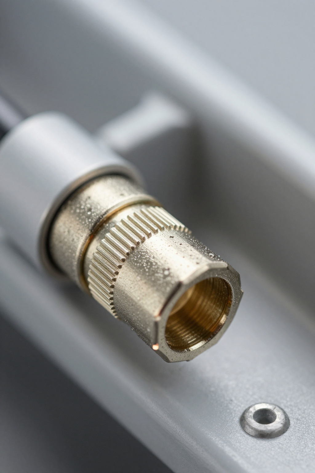
- Coupling type: push-to-seat quick-disconnect with positive latch and alignment features.
- Latch: metal over-molded actuator, retention force specified for blind mating tolerances.
- Overall dimensions & mounting envelope: compact flange footprint; panel cutout critical at the O-ring housing diameter.
- Sealing surfaces & tolerances: concentric seal faces with ±0.25 mm flatness; specify drawing callouts for panel/rack cutouts and screw boss clearance.
- Include small dimensional table or schematic callouts adjacent to the panel drawing for manufacturing.
Fluid & thermal interface specs
The liquid cooling interface lists rated fluids including DI water, glycol blends, and low-viscosity dielectric fluids with compatibility notes and recommended gasket materials. Operating temperature range and nominal internal volume are specified to estimate hold-up and thermal mass. Datasheet caveats include maximum recommended fluid viscosity and a lower temperature limit driven by seal material selection for long-term reliability.
(2) Compliance, standards & materials (data-analysis)
Standards & interoperability (OCP/UQD context)
The part references the UQD family naming and OCP-style interoperability notes, indicating backward-compatible mating with selected UQD variants and defined connector family nomenclature. Designers gain flexibility for upgrade paths when distribution manifolds follow the same interface. Interoperability implications include verifying latch geometry, sealing face location, and matched pressure ratings across mixed vendors in a rack loop.
Materials, plating & corrosion resistance
Wetted materials are listed with base metals, elastomers, and surface finishes; common finishes include nickel or passivation for corrosion resistance. For glycol blends use EPDM or FKM O-rings, while DI water often favors stable elastomers and plated metallic surfaces. Inspection intervals depend on coolant choice: dielectric fluids allow longer intervals, while glycol blends suggest visual and particulate checks quarterly in high-cycle systems.
| Component | Material Spec | Compatibility Note |
|---|---|---|
| Housing Body | Nickel-plated Brass | High corrosion resistance for glycol/DI mixtures |
| Primary Seal | EPDM (Ethylene Propylene Diene Monomer) | Standard for water/glycol; avoid aromatic hydrocarbons |
| Secondary Seal | FKM (Viton) | Higher temp tolerance; better chemical stability |
| Latch Spring | Stainless Steel 304 | Resistant to rust in humid edge environments |
(3) Thermal performance & test data (data-analysis)
Test methodology & conditions
The datasheet reports thermal performance from controlled loop tests: specified loop plumbing, repeatable flow rates, calibrated sensor placement upstream and downstream, and ambient conditions. Pressure-drop points and heat-load application methods are documented. To replicate results, mirror sensor locations and tubing ID, run steady-state durations long enough to reach thermal equilibrium, and log inlet/outlet temps plus flow and pressure simultaneously.
Performance curves & interpretation
Performance curves typically show pressure drop vs. flow, heat-transfer limits, and maximum sustainable flow. Interpret curves to define safe operating envelopes and derating for higher-viscosity fluids or elevated temperatures. Include a sample table or graph callout and note measurement uncertainty from flow meter accuracy and sensor placement; plan conservative margins for manifold and cold-plate assemblies.
(4) Installation & integration best practices (method guide)
Mechanical installation and torque / sealing procedures
Follow datasheet mounting guidance: use specified torque values where provided, align coupling faces before latch actuation, and avoid twist loads that can nick O-rings. Tighten fasteners incrementally and check seal compression visually. During assembly observe ESD controls for adjacent electronics and maintain clean-room-level cleanliness to prevent particulate inclusion that can compromise sealing and flow passages.
Fluid connection, leak testing & maintenance schedule
Recommended procedures include pressure hold tests at a defined test pressure for a given duration, bubble/leak detectors for rapid checks, and initial system flush to remove particulates. Use inline filtration during commissioning and schedule visual inspections and leak tests at regular intervals based on coolant and duty cycle. Signs requiring immediate service include pressure-drop shifts, particulate spikes, or external seepage at mating faces.
(5) Typical applications & use-case scenarios (case)
Rack-level and server integration
The part integrates into server cold-plate loops, distribution manifolds, and rack CDU interfaces where quick-disconnects enable hot-swap or maintenance. The compact mounting footprint supports dense trays and allows service access from the aisle. Designers should coordinate manifold layouts to minimize hose runs and specify mating retention clips for vibration-prone rack installations to avoid accidental decoupling during service.
Edge and high-density compute use cases
In edge deployments and compact chassis, reliable quick-disconnects permit higher TDP components by enabling directed liquid cooling where airflow is constrained. Consider environmental constraints: vibration, temperature swings, and limited service access dictate stiffer retention, corrosion-resistant finishes, and a planned spare-parts kit containing seals and mating caps for rapid swap-out in the field.
(6) Spec checklist & troubleshooting (action-oriented)
Pre-installation checklist
Print-ready checklist: verify part number and three-way mating part; confirm material compatibility with chosen coolant; confirm dimensional fit against panel and housing drawings; stock O-ring spares and mating caps; ensure required test equipment (pressure gauge, flow meter) is available; and validate torque tools and clean assembly area for contamination control prior to first install.
Common failure modes & troubleshooting steps
Frequent issues include seal damage from misalignment, incorrect mating orientation, or particulate-induced leaks; pressure-drop anomalies from partial blockage; and retention failures from worn latch components. Troubleshooting steps: isolate and recheck orientation, replace O-rings, flush the flow path, verify assembly torque, and if anomalies persist, escalate for part replacement and underlying manifold inspection.
Summary
Reviewing the UQDLS-04HSH03-L000 datasheet before procurement ensures mechanical fit, material compatibility, and thermal margins align with system requirements for liquid cooling. Validate interoperability in OCP-style loops, replicate datasheet test conditions in lab, and plan spares and maintenance intervals. Final action: confirm compatibility, test under target conditions, and maintain an O-ring and cap spares plan.
Key Summary
- The UQDLS-04HSH03-L000 datasheet provides critical dimensional and sealing callouts—verify panel cutouts and O-ring housing details before ordering parts to avoid rework and ensure rack fit.
- Thermal and fluid notes identify compatible coolants and viscosity derating—confirm coolant choice against listed materials and pressure-drop curves to meet flow and heat-transfer targets.
- Installation and maintenance guidance recommends pressure-hold leak tests, filtration and spare O-rings—establish service intervals and spare kits to reduce downtime in dense liquid cooling architectures.
FAQ
What should procurement verify on the UQDLS-04HSH03-L000 before purchasing?
Procurement must verify the exact part number, mating-family compatibility, material compatibility with the chosen coolant, dimensional fit against CAD cutouts, and availability of spares such as O-rings and dust caps. Confirm test reports and any specified pressure ratings align with upstream manifold and CDU specifications.
How should engineers replicate the datasheet thermal tests in a lab?
Replicate the reported loop by matching tubing ID, calibrated flow meters, sensor placement, and steady-state dwell times. Record inlet/outlet temperatures, flow rate, and pressure drop simultaneously. Use the same coolant or a conservative viscosity-equivalent substitute, and document any deviations to compute test uncertainty and derating.
What are the first signs of a failing quick-disconnect in a liquid cooling loop?
Early indicators include small external seepage at the mating face, an unexplained step change in loop pressure drop, particulate spikes downstream, or latch wear causing intermittent engagement. Immediate steps are to isolate the segment, perform a pressure-hold test, inspect and replace seals, and flush the loop before returning to service.
Is the UQDLS-04HSH03-L000 compatible with dielectric fluids?
Yes, the datasheet lists low-viscosity dielectric fluids as compatible. However, engineers must verify specific elastomer swelling properties. While DI water and glycol blends use standard EPDM/FKM seals, some specialized dielectrics may require different gasket materials to prevent long-term degradation. Always consult the material compatibility chart for your specific fluid brand.


