





Point: Three datasheet numbers determine performance: maximum flow rate, maximum working pressure, and operating temperature range. Evidence: Small deltas in any of these change pump head, allowable ΔT, and leak risk in rack liquid-cooling loops. Explanation: For example, a 10% higher flow demand raises pressure drop nonlinearly, stressing seals and increasing pump power—so these three metrics are the fastest path to system-level tradeoffs when reading the UQDS-04TMB02-L000 datasheet.
Point: This article translates the datasheet into engineer-actionable steps. Evidence: It explains how to read flow curves, verify mating and mechanical compatibility, and install with acceptance tests. Explanation: The goal is to let design engineers convert published numbers into pump sizing, thermal budgeting, and installation checklists quickly; meta description suggestion: "UQDS-04TMB02-L000 datasheet: extract flow specs, pressure limits, and install checks for reliable rack liquid cooling."
(1) Overview / Background: What the UQDS-04TMB02-L000 Is and Where It Fits
1.1 Connector family & function
Point: The part is a blind-mate quick-disconnect coolant coupling intended for modular rack and server coolant paths. Evidence: Datasheet sections labeled "connector type" and "application" show a sealed, push-to-mate body with integrated valve. Explanation: In practice, this class provides rapid hot-swap capability where mating occurs under pressure and alignment features ensure valve actuation only on full engagement; confirm variant codes in the datasheet when ordering to match valve or nozzle styles.
1.2 Typical applications & design priorities
Point: Typical use cases include rack-level supply/return modules, removable server trays, and hot-swap coolant distribution. Evidence: The datasheet emphasizes low pressure drop, leak-free blind mating, and materials compatible with common coolant chemistries. Explanation: Design priorities therefore focus on minimal ΔP to reduce pump sizing, robust seal chemistry for longevity, and mechanical guides to prevent misalignment during blind connects—these determine whether the part meets system uptime and maintenance targets.
(2) Flow Performance & Thermal Capacity — datasheet flow specs explained
2.1 Interpreting flow rate vs. pressure-drop curves
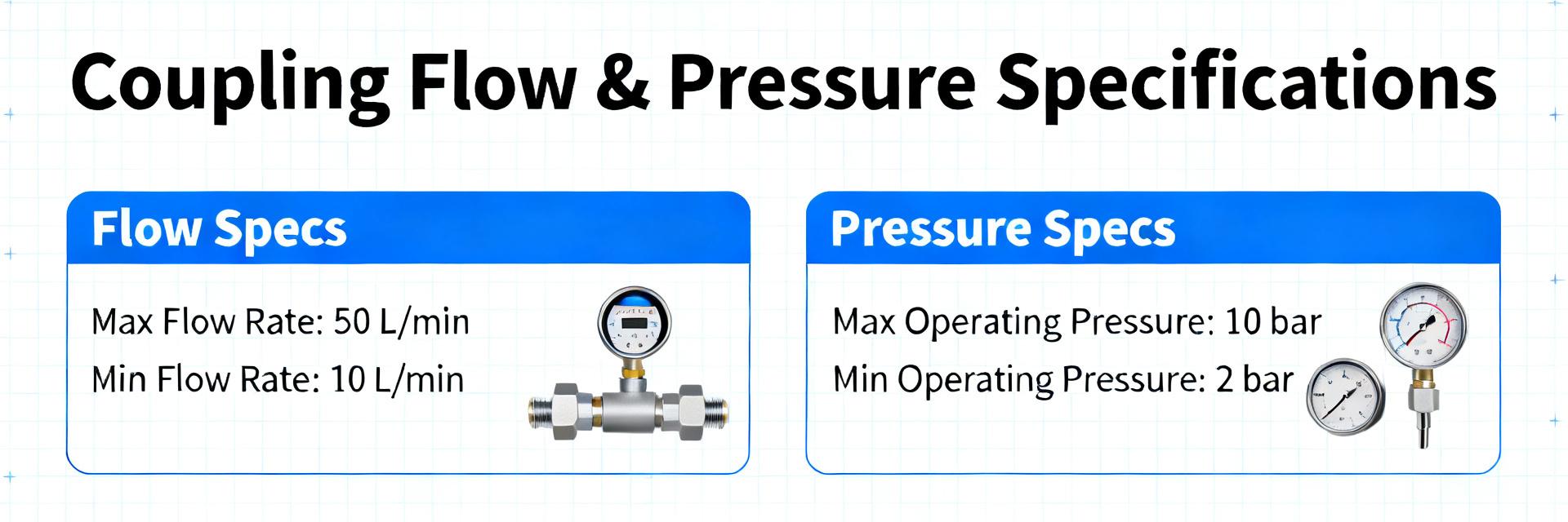
Point: Flow curves provide ΔP as a function of volumetric flow for a test fluid and temperature; reading axes and test conditions is essential. Evidence: A typical curve lists flow (L/min) on the x-axis and pressure drop (kPa) on the y-axis, with a note on test fluid viscosity and temperature. Explanation: To size a pump, pick the target flow, read ΔP, add hose and manifold losses, then ensure pump head exceeds total. Worked example: if the curve shows 0.8 kPa ΔP at 4 L/min through the coupling, and the line and manifold add 6 kPa, total head = 6.8 kPa; use margins for safety. Note: use “flow specs” as the principal input to this calculation.
2.2 Thermal capacity, coolant compatibility & impact on ΔT
Point: Convert flow to heat removal with Q = m·cp·ΔT; datasheet provides flow limits, so cp and density assumptions are needed. Evidence: If target device dissipates 400 W and coolant is water-like (ρ≈1000 kg/m³, cp≈4.18 kJ/kg·K), then 1 L/min yields roughly 0.07 kg/s, giving ΔT ≈ 1.4 K. Explanation: Use datasheet max continuous flow to compute maximum heat removal, then apply a safety margin (20–30%) to account for viscous fluids or fouling. Verify listed compatible fluids and temperature limits in the datasheet because higher viscosity or additives raise ΔP and reduce effective flow.
(3) Mechanical Dimensions, Materials & Ratings
3.1 Critical dimensions & mating compatibility
Point: Key dimensions—outer diameter, insertion depth, and mating tolerance—govern seal engagement and blind-mate reliability. Evidence: Dimensional drawings in the datasheet list nominal OD, recommended panel cutout, and minimum insertion depth with tolerance bands. Explanation: Verify counterpart geometry by checking pin alignment, guide features, and insertion limits; a tolerance stack-up of even 0.5 mm can compromise O‑ring squeeze and cause leaks, so capture these dims in the BOM and fixture drawings.
3.2 Materials, pressure & temperature ratings, seal types
Point: Materials and seals determine chemical compatibility and longevity under pressure/temperature cycles. Evidence: Datasheet material callouts typically include metal body alloy, plated finish, and elastomer seal type with operating temperature range and maximum working pressure. Explanation: Summarize rated WP and burst pressure from the datasheet and adopt a maintenance interval based on cyclic mating notes; if system pressure can exceed WP or fluid additives are present, choose alternate seals or restrict service life.
| Parameter | Representative Value (datasheet) |
|---|---|
| Max continuous flow | See flow curve (use design target) |
| Max working pressure | Confirm datasheet WP; do not exceed |
| Operating temperature | Per seal/material limits in datasheet |
| Materials | Metal body; elastomer seals (specify type) |
| Critical dimension | OD, insertion depth, mating tolerance per drawing |
(4) Field Use Cases & Deployment Examples (Case showcase)
4.1 Representative deployment: rack-level cooling scenario
Point: A realistic rack node dissipates ~400–800 W; connectors must supply flow to meet ΔT targets. Evidence: Choosing 4 L/min per connector at water-like coolant gives low ΔT per node and modest ΔP through the coupling. Explanation: In a rack with 10 nodes, distribute supply headers and use quick-disconnects at each tray; compute pump head by summing coupling ΔP (from flow curve), manifold losses, and elevation—then add 20% margin for fouling and viscosity increase.
4.2 Comparison vs. common quick-disconnect behaviors
Point: This variant typically trades low ΔP and blind-mate ease against compact form factor. Evidence: Compared to generic families, differences appear in seat design, valve poppet profile, and seal geometry that reduce ΔP at given flow. Explanation: Prefer this part when low ΔP and frequent hot swaps are primary; select alternative families when extreme chemistry or temperatures exceed the listed seal/material ratings.
(5) Implementation Checklist, Installation & Troubleshooting
5.1 Pre-installation & installation best practices
Point: Follow a concise checklist derived from datasheet notes to avoid installation-induced leaks. Evidence: Key steps include visual inspection, confirming part code, verifying O‑ring seating, correct insertion depth, and performing an initial low-pressure leak test. Explanation: Acceptance tests should include an initial pressurization to the specified test pressure, a cyclic mate/demate exercise for assembly wear, and post-thermal-cycle verification; use simple fixtures like a pressure rig and magnifier for inspection.
5.2 Common failure modes & troubleshooting flow/leak issues
Point: When flow specs are unmet or leaks occur, root causes are usually mechanical or fluid-related. Evidence: Typical faults include partial blockage, collapsed tubing, incorrect mating, incompatible seals, or trapped air. Explanation: Diagnostics: isolate the segment, measure static and dynamic pressures, inspect seals and mating faces, purge air, and if ΔP remains high consider cleaning or replacement. Decision guide: persistent pressure loss or visible seal extrusion → replace; intermittent leaks tied to cycling → inspect mating geometry and retorque or realign.
Summary & Next Steps
- Extract flow curves and WP from the datasheet and map to system pump head and heat load; record chosen operating point in the BOM and test plan using the UQDS-04TMB02-L000 values.
- Verify mechanical mating dimensions and seal materials against system tolerances and coolant chemistry; include mating fixtures in acceptance tests to prevent field leaks.
- Run bench pressure/flow tests and cyclic mate/demate sequences per checklist, document results, and adopt a maintenance interval based on cyclic life and fluid compatibility from the datasheet.
Frequently Asked Questions
How do I translate flow specs into pump head requirements?
Use the flow vs. pressure-drop curve to read the coupling ΔP at target flow, sum pipeline and manifold losses, then select a pump with head greater than the total plus a safety margin (typically 20–30%). Verify with a bench rig before deployment to account for viscosity and fouling.
What acceptance tests should validate an installed connector?
Perform a visual inspection, an initial low-pressure leak test to specified test pressure, a cyclic mate/demate sequence to simulate service, and a post-thermal-cycle leak check. Record flow and pressure readings and compare against datasheet limits; any deviation triggers inspection of seals and mating geometry.
When should I remove the connector from service?
Remove if observed leak rates exceed datasheet allowable limits, if pressure tests fail to hold, if ΔP at nominal flow increases beyond an agreed threshold, or if seals show extrusion or chemical degradation. Maintain replacement criteria in the maintenance plan tied to datasheet ratings.
Why is operating temperature critical for this component?
Operating temperature affects seal elasticity and fluid viscosity. Exceeding the rated range can cause seal hardening or creep, leading to leaks. Always verify the specific elastomer material's temperature limits in the datasheet before system integration.


