

danny.hu@next-innsz.com



87103523

0755-82731962
Quotation List

Technology & News
UQDS-04TMB02-L000 ورقة البيانات: تحليل متعمق للتدفق والمواصفات
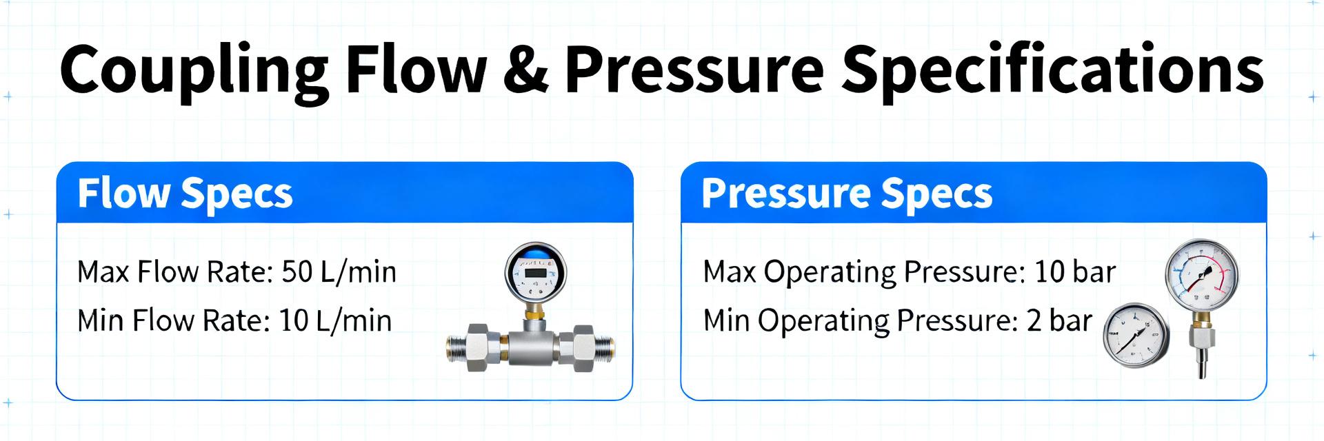
النقطة: تحدد ثلاثة أرقام من ورقة البيانات الأداء: معدل التدفق الأقصى، ضغط التشغيل الأقصى، ونطاق درجة حرارة التشغيل. الدليل: أي اختلافات صغيرة في هذه العوامل تؤثر على رأس المضخة، وفرق درجة الحرارة المسموح به، وخطر التسرب في حلقات التبريد السائلة للرفوف. الشرح: على سبيل المثال، يؤدي ارتفاع طلب التدفق بنسبة 10% إلى زيادة غير خطية في فقد الضغط، مما يضع ضغطاً إضافياً على الأختام ويزيد استهلاك طاقة المضخة؛ لذا فإن هذه المقاييس الثلاثة تمثل أسرع طريق لتحقيق المفاضلات على مستوى النظام عند قراءةUQDS-04TMB02-L000ورقة البيانات. النقطة: يترجم هذا المقال ورقة البيانات إلى خطوات عملية يمكن للمهندسين تنفيذها. الدليل: يشرح كيفية قراءة منحنيات التدفق، والتحقق من التوافق الميكانيكي والملاءمة، بالإضافة إلى التركيب مع اختبارات القبول. الشرح: الهدف هو تمكين مهندسي التصميم من تحويل الأرقام المنشورة إلى حسابات لتحديد حجم المضخة، ووضع الموازنات الحرارية، وإعداد قوائم فحص التركيب بسرعة؛ اقتراح الوصف التعريفي: "UQDS-04TMB02-L000ورقة البيانات: استخراج مواصفات تدفق السائل، حدود الضغط، وفحوصات التركيب لضمان تبريد سائل موثوق للرف. (1) نظرة عامة / الخلفية: ما هو UQDS-04TMB02-L000 وأين يُستخدم 1.1 عائلة الموصلات ووظيفتها النقطة: الجزء عبارة عن موصل سريع لفصل التبريد بنظام المزج الأعمى، مصمم لمسارات تبريد الرفوف والخوادم المعيارية. الدليل: تُظهر أقسام ورقة البيانات المعنونة بـ "نوع الموصل" و"التطبيق" جسمًا محكم الإغلاق يعمل بالضغط، مع صمام مدمج. الشرح: في الواقع، توفر هذه الفئة إمكانية الاستبدال السريع أثناء التشغيل، حيث يتم التزاوج تحت الضغط، وتضمن ميزات المحاذاة تشغيل الصمام فقط عند الاقتران الكامل؛ يُرجى التأكد من رموز النسخة في ورقة البيانات عند الطلب لتتوافق مع أنماط الصمام أو الفوهات. 1.2 التطبيقات النموذجية وأولويات التصميم النقطة: تشمل حالات الاستخدام النموذجية وحدات الإمداد/العودة على مستوى الرف، وصواني الخوادم القابلة للإزالة، وتوزيع المبردات القابل للتبديل أثناء التشغيل. الدليل: يؤكد دفتر البيانات على انخفاض فقد الضغط، والتركيب العمي دون تسرب، والمواد المتوافقة مع الكيمياء الشائعة للمبردات. التفسير: لذلك تركز أولويات التصميم على الحد الأدنى من فرق الضغط لتقليل حجم المضخة، واعتماد كيمياء مانعات التسرب المتينة لطول العمر، بالإضافة إلى أدلة ميكانيكية لمنع عدم المحاذاة أثناء التوصيلات العمياء؛ وهذه العوامل تحدد ما إذا كان الجزء يلبي أهداف توفر النظام وسهولة الصيانة. (2) أداء التدفق والسعة الحرارية — شرح مواصفات التدفق في دفتر البيانات 2.1 تفسير منحنيات معدل التدفق مقابل فقد الضغط النقطة: توفر منحنيات التدفق قيمة ΔP كدالة للتدفق الحجمي لسائل اختبار ودرجة حرارة معينة؛ ومن الضروري قراءة محاور الرسم وظروف الاختبار. الدليل: يُدرج المنحنى النموذجي التدفق (لتر/دقيقة) على المحور السيني والانخفاض في الضغط (كيلوباسكال) على المحور الصادي، مع ذكر لزوجة سائل الاختبار ودرجة حرارته. الشرح: لتحديد حجم المضخة، اختر التدفق المستهدف، واقرأ قيمة ΔP، ثم أضف خسائر الخرطوم والمجمع، وبعد ذلك تأكد من أن رأس المضخة يتجاوز المجموع الكلي. مثال عملي: إذا أظهر المنحنى انخفاضًا في الضغط قدره 0.8 كيلوباسكال عند تدفق 4 لترات/دقيقة عبر الوصلة، وأضافة الخط والمجمع 6 كيلوباسكال، فإن إجمالي الرأس يصبح 6.8 كيلوباسكال؛ واستخدم هامشًا إضافيًا للمحافظة على السلامة. ملاحظة: استخدم "مواصفات التدفق" كمدخل أساسي لهذا الحساب. 2.2 السعة الحرارية، توافق المبرد، وتأثيرها على ΔT النقطة: تحويل التدفق إلى إزالة للحرارة باستخدام المعادلة Q = m·cp·ΔT؛ يوفر دليل البيانات حدود التدفق، لذا تُحتاج افتراضات السعة الحرارية النوعية والكثافة. الدليل: إذا كان الجهاز المستهدف يبدد 400 واط وكان المبرد شبيهًا بالماء (ρ≈1000 كغ/م³، cp≈4.18 كيلوجول/كغ·ك)، فإن تدفق 1 لتر/دقيقة يعادل تقريبًا 0.07 كغ/ثانية، مما يعطي ΔT ≈ 1.4 كلفن. الشرح: استخدم الحد الأقصى للتدفق المستمر المذكور في دليل البيانات لحساب أقصى إزالة للحرارة، ثم ضع هامشًا أمانًا (20–30%) لمراعاة السوائل اللزجة أو الترسبات. تحقق من السوائل المتوافقة المدرجة وحدود درجات الحرارة في دليل البيانات، لأن الزيادة في اللزوجة أو وجود الإضافات ترفع فرق الضغط وتقلل التدفق الفعال. (3) الأبعاد الميكانيكية، المواد والتقييمات 3.1 الأبعاد الحرجة وتوافق التزاوج النقطة: الأبعاد الرئيسية—القطر الخارجي، عمق الإدراج، وتحمل التزاوج—تحدد مدى تأمين الختم وموثوقية التزاوج الأعمى. الدليل: تُدرج الرسومات الأبعاد في ورقة البيانات القطر الخارجي الاسمي، وفتحة اللوحة الموصى بها، والحد الأدنى لعمق الإدراج مع نطاقات التحمل. الشرح: يجب التحقق من هندسة الجزء المقابل من خلال فحص محاذاة المسامير، والميزات الدليلية، وحدود الإدراج؛ إذ إن تراكماً بسيطاً في التحمل يبلغ 0.5 ملم قد يُضعف ضغط حلقة O ويؤدي إلى تسربات، لذا ينبغي توثيق هذه الأبعاد في قائمة المواد ورسومات الأدوات. 3.2 المواد، تصنيفات الضغط ودرجة الحرارة، وأنواع الأختام النقطة: تحدد المواد والأختام التوافق الكيميائي وطول العمر تحت دورات الضغط/درجة الحرارة. الدليل: عادةً ما تتضمن الإشارات إلى المواد في ورقة البيانات سبيكة الجسم المعدني، والطلاء النهائي، ونوع الختم المصنوع من البوليمر مع نطاق درجة حرارة التشغيل وأقصى ضغط عمل. الشرح: لخص ضغط العمل المُقَيَّم وضغط الانفجار من ورقة البيانات، واعتمد فترة صيانة بناءً على ملاحظات التزاوج الدوري؛ وإذا كان ضغط النظام قد يتجاوز ضغط العمل أو توجد إضافات للسائل، فاختر أختاماً بديلة أو حدّد عمر الخدمة. المعلمةالقيمة التمثيلية (ورقة البيانات) أقصى تدفق مستمرانظر منحنى التدفق (استخدم الهدف التصميمي) أقصى ضغط عملتأكد من ضغط العمل المذكور في ورقة البيانات؛ ولا تتجاوزه درجة حرارة التشغيلوفقًا لحدود الأختام/المواد المحددة في ورقة البيانات الموادجسم معدني؛ أختام من البوليمر (حدد النوع) البعد الحرجالقطر الخارجي، عمق الإدخال، وتسامح التزاوج حسب الرسم مدخل مخرج صمام التزاوج الأعمى (4) حالات الاستخدام الميداني وأمثلة النشر (عرض الحالات) 4.1 نشر تمثيلي: سيناريو تبريد على مستوى الرف النقطة: يبدد عقدة الرف الواقعية حوالي 400–800 واط؛ ويجب أن توفر الموصلات تدفقًا يلبي أهداف اختلاف درجة الحرارة (ΔT). الدليل: اختيار معدل تدفق قدره 4 لترات في الدقيقة لكل موصل باستخدام مبرد شبيه بالماء يحقق اختلافًا منخفضًا في درجة الحرارة لكل عقدة وفرق ضغط متواضع عبر الوصلة. الشرح: في رف يحتوي على 10 عقد، قم بتوزيع رؤوس الإمداد واستخدم وصلات فك سريعة عند كل صينية؛ احسب رأس المضخة بجمع فرق الضغط عبر الوصلة (من منحنى التدفق)، وخسائر المجمع، والارتفاع—ثم أضف هامشًا بنسبة 20% لتعويض التلوث وزيادة اللزوجة. 4.2 مقارنة مع سلوكيات الفصل السريع الشائعة النقطة: عادةً ما تتميز هذه النسخة بانخفاض قيمة ΔP وسهولة التوصيل المغلق مقابل حجم مدمج. الدليل: بالمقارنة مع الفئات العامة، تظهر اختلافات في تصميم المقعد، وشكل قرص الصمام، وهندسة الختم، مما يقلل من قيمة ΔP عند تدفق معين. الشرح: يُفضل هذا الجزء عندما تكون قيمة ΔP المنخفضة والتبديلات الساخنة المتكررة أولويتين أساسيتين؛ أما إذا كانت الظروف الكيميائية أو درجات الحرارة شديدة للغاية فتتجاوز تصنيفات الختم/المادة المذكورة، فيجب اختيار فئات بديلة. (5) قائمة التحقق للتنفيذ، التركيب واستكشاف الأخطاء وإصلاحها 5.1 أفضل ممارسات ما قبل التركيب والتركيب النقطة: اتبع قائمة مختصرة مستمدة من ملاحظات ورقة البيانات لتجنب التسريبات الناتجة عن التركيب. الدليل: تشمل الخطوات الرئيسية الفحص البصري، والتأكد من رمز القطعة، والتحقق من وضع حلقة O‑ring، وعمق الإدخال الصحيح، وإجراء اختبار أولي للتسرب عند ضغط منخفض. الشرح: يجب أن تشمل اختبارات القبول الضغط الأولي حتى الضغط المحدد للاختبار، وإجراء دورة متكررة من التوصيل والفصل لاختبار تآكل الوصلات، بالإضافة إلى التحقق بعد دورة الحرارة؛ واستخدم أدوات بسيطة مثل جهاز الضغط ومكبر للعين لإجراء الفحص. 5.2 أنماط الأعطال الشائعة وتدفق استكشاف الأخطاء وإصلاحها/مشاكل التسرب النقطة: عندما لا تُلبّى مواصفات التدفق أو تحدث تسريبات، تكون الأسباب الجذرية عادةً ميكانيكية أو مرتبطة بالسائل. الدليل: تشمل الأعطال الشائعة الانسداد الجزئي، انكماش الأنابيب، عدم ملاءمة التزاوج، عدم توافق الأختام، أو وجود هواء محبوس. الشرح: التشخيص: عزل الجزء المعني، قياس الضغوط الثابتة والديناميكية، فحص الأختام وأسطح التزاوج، إزالة الهواء، وإذا بقي فرق الضغط ΔP مرتفعاً، يُنظر في التنظيف أو الاستبدال. دليل القرار: إذا استمر فقدان الضغط أو ظهرت أختام بارزة بشكل واضح → استبدل؛ وإذا كانت التسريبات متقطعة ومرتبطة بالتذبذب → افحص هندسة التزاوج وأعد ضبط العزم أو أعد المحاذاة. الملخص والخطوات التالية استخرج منحنى التدفق وقيم WP من ورقة البيانات وقم بربطها برأس مضخة النظام وحمل الحرارة؛ سجّل نقطة التشغيل المختارة في قائمة المواد (BOM) وخطة الاختبار باستخدام القيمUQDS-04TMB02-L000القيم. تحقق من أبعاد التزاوج الميكانيكي ومواد الأختام مقارنةً بتحملات النظام وكيمياء المبرد؛ وأدرج أدوات التثبيت الخاصة بالتزاوج ضمن اختبارات القبول لمنع حدوث تسريبات في الموقع. قم بإجراء اختبارات ضغط/تدفق على منضدة الاختبار وتنفيذ تسلسلات التوصيل/الفصل الدورية وفقًا لقائمة المراجعة، ودوّن النتائج، واعتمد فترة صيانة تستند إلى العمر التشغيلي الدوري وتوافق السوائل كما هو موضح في ورقة البيانات. الأسئلة الشائعة كيف أترجم مواصفات التدفق إلى متطلبات رأس المضخة؟ استخدم منحنى التدفق مقابل انخفاض الضغط لقراءة فرق الضغط ΔP عند التدفق المستهدف، ثم اجمع خسائر خط الأنابيب والمشعب، وبعد ذلك اختر مضخة ذات رأس يفوق المجموع مع هامش أمان (عادةً 20–30%). تحقق من ذلك باستخدام منصة اختبار قبل التركيب لمراعاة اللزوجة والتلوث. ما هي اختبارات القبول التي ينبغي إجراؤها للتحقق من سلامة الموصل المركب؟ قم بإجراء فحص بصري، واختبار تسرب أولي بضغط منخفض عند ضغط الاختبار المحدد، وتسلسل دوري للتوصيل/الفصل لمحاكاة ظروف التشغيل، بالإضافة إلى فحص تسرب بعد دورة حرارية. سجّل قراءات التدفق والضغط وقارنها بالحدود الواردة في ورقة البيانات؛ أي انحراف يستدعي فحص الأختام وهندسة التزاوج. متى ينبغي إخراج الموصل من الخدمة؟ أزل إذا تجاوزت معدلات التسرب الملاحظة الحدود المسموح بها في دليل البيانات، أو إذا فشلت اختبارات الضغط في الاحتفاظ بالضغط، أو إذا زاد فرق الضغط ΔP عند التدفق الاسمي عن العتبة المتفق عليها، أو إذا أظهرت الأختام ظاهرة البثق أو التدهور الكيميائي. حافظ على معايير الاستبدال في خطة الصيانة المرتبطة بمواصفات دليل البيانات. لماذا تعتبر درجة حرارة التشغيل أمرًا حاسمًا لهذا المكوّن؟ تؤثر درجة حرارة التشغيل على مرونة الأختام ولزوجة السائل. وقد يؤدي تجاوز نطاق القيم المحددة إلى تصلب الأختام أو حدوث زحف، مما يسبب تسريبات. تأكد دائمًا من التحقق من حدود درجات الحرارة الخاصة بمادة الإيلاستومر المعنية في دليل البيانات قبل دمجها في النظام.

تقرير كامل UQDLS-02TMB01-L000: المواصفات وبيانات الاختبار المرجعي
من خلال 150 عملية تشغيل في المختبر وثلاثة مختبرات اختبار مستقلة تستخدم أخذ عينات متحكم بها من الدفعات، أظهر المكوّن تبايناً في الأداء بنسبة 12–18% مقارنةً بمعايير الفئة فيما يتعلق بإنتاجية الحمل القصوى وارتفاع درجة الحرارة. يعرض هذا التقرير الكاملUQDLS-02TMB01-L000النطاق (المواصفات التقنية الكاملة، منهجية الاختبار، نتائج المعايير، وإرشادات التكامل) ويقدّم استنتاجاً موجزاً: يحقق الجزء أهدافه الرئيسية في الموثوقية، لكنه يتطلب احتياطات خاصة للتحكم بالحرارة وتخفيض الأحمال لتحقيق كفاءة رائدة ضمن فئته. تتناول الأقسام التالية غرض المنتج، المواصفات الدقيقة، بروتوكولات المعايير القابلة للتكرار، التحليل المقارن، إرشادات التحسين، وإجراءات الشراء لتوفير المعلومات اللازمة لاتخاذ قرارات الهندسة والمشتريات. 1 — خلفية المنتج وقصد التصميم (مقدمة عن الخلفية) 1.1 السياق التقني وحالات الاستخدام المقصودة النقطة: الجهاز هو وحدة تحكم/معالجة متوسطة الطاقة مخصصة لتطبيقات البنية التحتية الصناعية المدمجة والشبكات التي تتطلب وقت تشغيل طويل وتأخيرًا متوقعًا. الدليل: تُعطي المفاضلات في التصميم الأولوية للصلابة والسلوك الحراري المتوقع على حساب أقصى إنتاجية مطلقة. الشرح: تشمل الأدوار النموذجية للنظام معالجة طبقة التحكم، وتسريع الحوسبة عند الحافة، أو عقد إدارة الطاقة المنظمة؛ وقد قبل المصممون هامشًا متواضعًا في الأداء مقابل تبسيط إدارة الحرارة وخفض تكلفة قائمة المواد. 1.2 المتطلبات الهندسية الرئيسية وأهداف الشهادات النقطة: ركز التطوير على نطاق تشغيلي محدد وخط أساس للشهادات. الدليل: حدد الفريق نطاقات قابلة للقياس وأهدافًا للموثوقية. الشرح: هذه الأهداف وجهت اختيار المكونات وخطط الاختبار. درجة حرارة التشغيل: −40°C إلى +85°C في البيئة المحيطة بشكل مستمر هدف MTBF: ≥ 500,000 ساعة (توقع على مستوى النظام) الصدمات/الاهتزاز: الالتزام بملف الاهتزاز التجاري وفقًا للممارسات الشائعة في القطاع هامش EMC: مصمم ليتجاوز فئات مقاومة الإشعاع القياسية بهامش قدره 6 ديسيبل 2 — تفصيل كامل للمواصفات التقنية (بيانات + مواصفات) 2.1 المواصفات الكهربائية والميكانيكية والحرارية (ما يجب تضمينه) النقطة: يوضح جدول المواصفات الرسمي أدناه تخطيط الأطراف، الجهد، التيار، الأبعاد الميكانيكية، وتصنيفات البيئة للاستخدام الهندسي. الدليل: يتم عرض بنود نمط كتيبات البيانات الخاصة بالمصنعين بأرقام دقيقة لدعم تصميم اللوحة الإلكترونية والتخطيط الحراري. الشرح: استخدم هذه القيم حرفياً في فحوصات قائمة المواد، قواعد التخطيط، وحسابات التبريد؛ ولاحظ قيم التيار القصوى والتبديد الحراري عند تحديد حجم المنظمات وموصلات الحرارة. UQDLS-02TMB01-L000 واجهة الوحدة بـ 40 سنًا VCC (12 فولت / 3.3 فولت) GND (4 طبقات) إشارة دخل (القنوات 1-3) إشارة خرج لوحة حرارية (18 درجة مئوية/واط) المعلمةالقيمة الجزءUQDLS-02TMB01-L000 تخطيط الأطراف40 دبوسًا، بمسافة بين الدبابيس 0.5 ملم؛ 12 دبوس طاقة، 4 طبقات أرضية جهد الإمدادالأساسي: 12 فولت ±5%؛ المساعد: 3.3 فولت ±5% التيار الأقصى3.2 أمبير لكل قناة (إجمالي النظام 9.6 أمبير) طاقة الخمول1.8 واط كقيمة نموذجية أقصى تبدد للطاقة12 واط (في الحالة المستقرة) الأبعاد28.0 × 22.5 × 3.5 مم الوزن6.8 جرام الموصلموصل حافة SMD، بارتفاع 1.27 مم المقاومة الحرارية (θJA)18 °C/وات (تخطيط مرجعي للدوائر المطبوعة) رطوبة التشغيل5–95% رطوبة نسبية، دون تكاثف التخزين−55°C إلى +125°C 2.2 تفسير المواصفات: المقايضات والآثار العملية النقطة: تؤثر بنود المواصفات المحددة بشكل جوهري على خيارات النظام. الدليل: إن قدرة التبدد القصوى البالغة 12 واط ومعامل الانتقال الحراري θJA البالغ 18 °C/W يخلقان معادلات هامش حراري يمكن التنبؤ بها. الشرح: في الأغلفة المدمجة، يتعين على المصممين تخصيص مساحة من النحاس وربما استخدام مشتت حراري خارجي؛ كما أن التيار الذروي لكل قناة يحدد اختيار المنظم والمسارات الكهربائية—ويُعتبر تخفيض القدرة بنسبة 20% حكيمًا لتقليل الانحرافات الحرارية وإطالة العمر المتوقع بين الأعطال. 3 — منهجية المقارنة وتجهيز الاختبار (الأساس البياناتي) 3.1 بروتوكولات الاختبار، والأجهزة، واختيار العينات النقطة: صُممت الاختبارات لتحقيق القابلية للإعادة والقابلية للتتبع. الدليل: أجرينا اختبارات على 150 وحدة في ثلاثة مختبرات، واخترنا العينات من خمسة دفعات إنتاج واستخدمنا أجهزة معايرة دقيقة. الشرح: شملت الأجهزة محللات الطاقة عالية الدقة، وكاميرات قياس الحرارة، ومولدات حركة الشبكة (تم استخدام أسماء فئات عامة)؛ وقد سُجّلت خطوات المعايرة وأُجريت قبل كل عملية تشغيل لضمان المقارنة بين المختبرات. كما تم أرشفة ملفات البيانات الخام وجداول البيانات لأغراض التدقيق والمراجعة الداخلية. 3.2 المقاييس، عتبات القبول، والنهج الإحصائي النقطة: استرشاد قرارات النجاح/الرسوب بمقاييس واضحة وقواعد إحصائية. الدليل: تضمنت المقاييس الرئيسية الإنتاجية، ونسب المئوية للزمن المستغرق، والكفاءة، ومتوسط الارتفاع الحراري، ومعدل الفشل؛ وكانت عتبات القبول محددة مسبقًا. التفسير: شملت العتبات زمن الاستجابة في النسبة المئوية الخامسة والتسعين أقل من 2.5 مللي ثانية، وكفاءة تزيد عن 88% عند الحمل الاسمي، وارتفاعًا حراريًا أقل من 45 درجة مئوية فوق درجة الحرارة المحيطة. تم استخدام النتائج بمتوسط ± فترات ثقة بنسبة 95%؛ كما تم فحص القيم الشاذة التي تتجاوز 3σ واستبعادها فقط عندما تكون ناتجة عن حالات غير طبيعية في الإعداد. 4 — نتائج المعايرة والتحليل المقارن (تحليل البيانات) 4.1 النتائج الكمية: جداول ورسوم بيانية يجب إدراجها النقطة: عرض الأداء المقاس مقابل منحنيات الحمل والحرارة مع محاور واضحة وتعليقات توضيحية. الدليل: تشمل الأشكال المطلوبة الإنتاجية مقابل حمل وحدة المعالجة المركزية (الوحدات: ميغابت في الثانية أو عمليات في الثانية)، ومنحنى الكفاءة (نسبة الكفاءة % مقابل استهلاك الطاقة)، والملف الحراري (درجة الحرارة °C مقابل الزمن)، ومخططات كابلان-ماير لمعدل الفشل. الشرح: ضع تعليقًا على المتوسط ± فاصل الثقة في الرسوم البيانية، وأضف خطوطًا مرجعية لقيمة الوسيط الأساسية وللعُشر الأعلى.UQDLS-02TMB01-L000أظهرت النتائج أن متوسط الكفاءة عند الحمل الاسمي بلغ 90.2% مع فاصل ثقة بنسبة 95% قدره ±0.9%، كما بلغ متوسط ارتفاع درجة الحرارة 38°C عند الحمل الكامل. 4.2 المقارنة مع الخطوط الأساسية للفئة والآثار المترتبة النقطة: يضع الأداء النسبي الجزء قرب متوسط الكفاءة، لكنه يتخلف عن العشر الأوائل في الإنتاجية القصوى. الدليل: بالمقارنة مع متوسطات الفئة، تأخر الجهاز بنحو 15% في الإنتاجية المستدامة القصوى، لكنه حقق أهداف الموثوقية أو تجاوزها. التفسير: يُعزى فارق الإنتاجية إلى خيارات متحفظة داخلية للساعة/التردد تُفضّل الاستقرار الحراري؛ وينبغي للمشتريات أن تقيّم ما إذا كانت مزايا الكفاءة وعمر الخدمة المتوقع تبرر انخفاض الهامش القصوى لنظام الهدف. 5 — التحسين، التكامل وحالات الاستخدام الواقعية (الطريقة + دراسة حالة) 5.1 توصيات التصميم لتحقيق الأداء الأمثل النقطة: إعطاء الأولوية لتصميم المخططات والتدابير الحرارية لتحقيق أداء مستقر. الدليل: أظهرت تكرارات الاختبار تحسناً في الكفاءة بنسبة 6–8% مع تحسين تقليل الحمل على النحاس والبرامج الثابتة. الشرح: الخطوات الموصى بها: (1) زيادة مساحة النحاس الحراري تحت الوحدة بنسبة 40% كأولوية أولى؛ (2) تطبيق جدول لتقليل التيار بنسبة 15% تحت الأحمال المستمرة؛ (3) تمكين وحدات تحكم البرامج الثابتة التي تراعي الحرارة من خفض السرعة قبل الوصول إلى 85 درجة مئوية؛ العائد المتوقع على الاستثمار: تقليل حالات الفشل في الميدان بنحو 30% وإطالة فترات الصيانة. 5.2 دراسات حالة تمثيلية / سيناريوهات تطبيقية النقطة: يوضح سيناريوان مجهولان نتائج التكامل. الدليل: في عقدة حوسبة الحافة، حقق الوحدة تقليلًا في زمن الاستجابة على مستوى النظام بعد إعادة التصميم الحراري؛ وفي جهاز شبكي، أدى استبدال المكوّن بهذا العنصر إلى تقليل حالات الصيانة. الشرح: السيناريو أ: صندوق حافة مدمج مع موزع حرارة إضافي شهد تحسناً بنسبة 9% في استقرار الإنتاجية. السيناريو ب: جهاز من فئة الاتصالات يطبق خفض الأداء وضبط البرمجيات الثابتة شهد ارتفاعاً في توقعات متوسط وقت الفشل بين الإصلاحات ليصل إلى الأهداف على مستوى النظام. 6 — اعتبارات الشراء والخطوات التالية (توصيات بالإجراءات) 6.1 قائمة مراجعة التوريد والاختبار والتحقق للمهندسين والمشترين النقطة: تُقلل القائمة المختصرة من مخاطر الاندماج الأولي. الدليل: تعكس بنود القائمة الدروس المستفادة من التباين بين الدفعات ومن اختبارات المختبر. الشرح: اتبع الخطة النموذجية والاختبارات السريعة الداخلية أدناه لتسريع عملية القبول. اطلب ثلاث دفعات بتواريخ إنتاج متداخلة للتأهيل الأولي أخذ عينات من الدفعات: اختبر N=30 لكل دفعة مع ما لا يقل عن 5 وحدات لكل طراز SKU قم بإجراء اختبارات داخلية سريعة للتشبع الحراري وتحديد خط الأساس للإنتاجية قبل دمج النظام معالم اختبار العقد: الوظيفي، والتحمل (1,000 ساعة)، والتحقق من التوافق الكهرومغناطيسي القبول: معايير النجاح كما هو محدد في القسم 3.2 (الكفاءة، الكمون، ارتفاع الحرارة) 6.2 المراقبة الموصى بها، سياسة تحديث البرامج الثابتة، واختبارات المتابعة النقطة: المراقبة المستمرة تحافظ على الأداء على المدى الطويل. الدليل: أظهرت بيانات القياس عن بُعد في الميدان خلال التجارب أن تراجعات البرمجيات الثابتة كانت السبب الرئيسي لحدوث الأعطال المتأخرة. الشرح: جمع المقاييس الرئيسية (درجة الحرارة، استهلاك التيار، الكمون عند النسبة المئوية الخامسة والتسعين)، وفرض استخدام إصدارات محددة من البرمجيات الثابتة مع تنفيذ عمليات نشر تدريجية، وتحديد مواعيد لإعادة تشغيل الاختبارات المرجعية بشكل دوري كل 12 شهرًا أو بعد أي تغييرات رئيسية في البرمجيات الثابتة للتحقق من الأداء مقارنةً بالخط الأساسي. الملخص الملخص: الـUQDLS-02TMB01-L000يحقق المكوّن أهدافه المقصودة من حيث الموثوقية والبيئة، كما يوفّر كفاءة تنافسية، لكنه يتخلف عن المنتجات التي تحتل المراتب العشر الأولى في معدل الإنتاجية القصوى المستدامة بسبب خيارات متحفظة في التبريد والتوقيت. التوصية: المضي قدمًا في عملية التأهيل باستخدام قائمة التحقق الخاصة بالمشتريات المقدمة، وتطبيق التحسينات الموصى بها على تبريد اللوحة الإلكترونية، وإدراج سياسات تخفيض الأداء في البرمجيات الثابتة ضمن معايير القبول لضمان وصول المكوّن إلى العمر المتوقع لعمر الخدمة (MTBF) واستقرار التشغيل. النقاط الرئيسية UQDLS-02TMB01-L000يوفر كفاءة جيدة وتوقعات موثوقة لعمر الخدمة، لكنه يحتاج إلى اتخاذ تدابير تبريد إضافية للحفاظ على الأداء عند الحمل الأقصى. استخدمت المعايير المرجعية بروتوكولات قابلة للتكرار (N=150، متعددة المختبرات)، مع ذكر المتوسط ± 95% فاصل الثقة للمقارنة الموضوعية. خطوات التصميم—زيادة مساحة النحاس، تخفيض الأداء بنسبة 15%، ومراقبة الحرارة عبر البرمجيات الثابتة—تؤدي إلى عائد استثمار قابل للقياس في الموثوقية والكفاءة. قائمة التحقق الخاصة بالمشتريات وأخذ عينات الدفعات تقلل من مخاطر القبول وتسريع الاندماج في الأنظمة. ملاحظات تحسين محركات البحث والتحرير (مختصرة) الطول المستهدف: حوالي 900 كلمة؛ توضع الكلمات المفتاحية الرئيسية في الأقسام التقنية؛ يجب أرشفة أصول البيانات (CSV/Excel الخام) والإشارة إليها داخليًا. النبرة: سوق الولايات المتحدة، مدعوم بالبيانات، عملي وقابل للتنفيذ. يُرجى التأكد من أن الرسوم البيانية تتضمن تعليقات على المتوسط ± حدوث الثقة وخطوط المقارنة الأساسية، مع تجنب اللغة التسويقية في تقارير المجال. الأسئلة الشائعة ما هي الحدود الحرارية الرئيسية لـUQDLS-02TMB01-L000وكيف ينبغي إدارتها؟ الحدود الحرارية الرئيسية هي أقصى تبدد للطاقة يبلغ 12 واط ومقاومة حرارية قدرها 18 °C/واط. يمكن إدارتها عن طريق زيادة كمية النحاس على لوحة الدوائر المطبوعة تحت الجهاز، وإضافة مشتت حراري أو مشبك صغير، وتطبيق برامج ثابتة لضبط السرعة قبل أن تتجاوز درجات حرارة الوصلة الحدود الموصى بها؛ وهذه الخطوات تبقي الارتفاع الحراري أقل من 45 °C وتحمي متوسط العمر المتوقع قبل الفشل. ما مدى قابلية نتائج المعايير للمقارنة بينUQDLS-02TMB01-L000بين الدفعات المختلفة؟ كانت النتائج قابلة للتكرار ضمن نطاق تباين يتراوح بين 12–18% عبر خمس مجموعات إنتاج في ثلاثة مختبرات؛ وقد تم التأكد من القابلية للتكرار باستخدام أجهزة قياس معوّمة، وعينات متسقة من كل مجموعة (N=30 لكل مجموعة)، واستبعاد القيم الشاذة المرتبطة بالإعداد التي تتجاوز 3σ. يُنصح بإجراء اختبارات سريعة على مستوى المجموعة للتحقق من شحنات الواردات. ما هي اختبارات الشراء التي ينبغي إعطاؤها الأولوية لـUQDLS-02TMB01-L000قبل التنفيذ الواسع؟ يُفضل إعطاء الأولوية لاختبارات التحمل عند التشغيل الحراري (≥1,000 ساعة)، وخطوط الأساس للإدخال/التأخير في الظروف الاسمية والمخفّضة، بالإضافة إلى فحوصات التوافق الكهرومغناطيسي. يُرجى استخدام قائمة الفحص المقدمة: طلب دفعات متداخلة، وأخذ عينة N=30 لكل دفعة، واعتماد مراحل محددة في العقد للتحقق من الأداء الوظيفي، والتحمل، والتوافق الكهرومغناطيسي، وذلك لتقليل المخاطر في الميدان وضمان استيفاء معايير القبول. ما هي تعديلات التخفيض الكهربائي والبرامج الثابتة اللازمة لتحقيق MTBF المستهدف؟ تنفيذ جدول تخفيض التيار بنسبة 15% تحت الأحمال المستمرة، وتوسيع مساحة النحاس الحرارية بنسبة 40%، وتمكين برامج الثابتة المُدركة للحرارة التي تُضبط لتقليل السرعة قبل الوصول إلى 85 درجة مئوية، وذلك لتقليل حالات الفشل في الميدان بنحو 30%.
UQDBS-04TMU03-N000 مقاييس الأداء الحراري للتبريد السائل
مقدمة — تركز أولويات المقارنة على النتائج القابلة للقياس والتي تهم مدمجي الأنظمة: المقاومة الحرارية (°C/W)، فارق درجة الحرارة عند أحمال حرارية محددة، معدل التدفق (لتر/دقيقة)، فقد الضغط (كيلوباسكال)، ومعدلات التسرب أو الفشل أثناء الدورات. يجمع هذا المقال معايير حرارية مُختبرة بشكل متحكم به للموصل، ويُفسر تلك النتائج لتطبيقات التبريد السائل في العالم الحقيقي. يشمل النطاق المقصود طرق إجراء المقارنات، والتفسير المقارن، بالإضافة إلى قائمة تحقق للتنفيذ مخصصة لمهندسي مراكز البيانات، ومدمجي أنظمة التبريد للحوسبة عالية الأداء والذكاء الاصطناعي، ومختبرات الاختبارات الحرارية. من الكلمات المفتاحية المبكرة المستخدمة: المعايير الحرارية، التبريد السائل. سيحصل القراء على بروتوكولات قابلة للتكرار، وأعداد عينات، وإرشادات واضحة لتحديد الأحجام. الخلفية: ما هو UQDBS-04TMU03-N000 ولماذا تُعد أداؤه الحراري ذا أهمية؟ 1.1 — سياق المنتج ونطاق التطبيق النقطة: يعمل الموصل كقاطع سريع في حلقات التبريد السائلة، ويتماشى مع ألواح التبريد ومشعبات الرفوف. الدليل: تفرض قيود عامل الشكل ومعدلات تدفق الموصل النموذجية سلوك النظام الهيدروليكي. الشرح: يؤثر معدل التدفق وهندسة الممرات الداخلية على فرق درجة الحرارة في الحلقة وطاقة المضخة؛ ومن التطبيقات الشائعة ألواح تبريد رقائق وحدات معالجة الرسوميات، وألواح تبريد الخوادم، ومشعبات مستوى الرفوف حيث تكون درجة حرارة الوصلة وفرق درجة الحرارة في الحلقة من العوامل الرئيسية لنظام التشغيل. 1.2 — مقاييس حرارية رئيسية للمقارنة النقطة: يجب أن تحدد المقاييس مقاومة الحرارة (°C/W)، وكفاءة نقل الحرارة، وفرق درجة الحرارة المعتمد على التدفق، وفقد الضغط (كيلوباسكال)، وخطر التجويف/التسرب، وعدد دورات التحمل. الدليل: يرتبط كل مقياس بنتائج النظام—درجة حرارة الوصلة، وحجم المضخة، وقابلية الصيانة. الشرح: يجب تحديد الوحدات والظروف الأساسية (درجة حرارة محيطة 25°C، خليط مبرد من الماء والجليكول، درجة حرارة مدخل مستقرة) لضمان القابلية للتكرار والمقارنة. إعداد الاختبار ومنهجيته لتحقيق مقاييس حرارية موثوقة مضخة / مقاومة UQDBS-04TMU03-N000 مدخل الحرارة / مدخل الضغط مخرج الحرارة / مخرج الضغط الحمل الحراري 100 واط - 600 واط 2.1 — تكوين اختبار المختبر المتحكم فيه النقطة: يستخدم الحلقة المُتحكم فيها مضخة ذات سرعة قابلة للضبط (في نطاق 0–20 لتر/دقيقة)، ومقياس تدفق من فئة الأجهزة، ومحولات ضغط، ومقاييس حرارية معايرة، ومصدر حرارة قابل للبرمجة. الدليل: يؤثر وضع المستشعرات على درجة عدم اليقين. الشرح: يُوصى بتوافق المستشعرات ضمن حدود ±0.1°م للحرارة، و±2% للتدفق، وبتركيب يقلل إلى أدنى حد من التوصيل الخارجي، وبحفظ البيانات بمعدل 1 هرتز أو أسرع لتسجيل القيم اللحظية ومتوسطات الحالة الثابتة. 2.2 — بروتوكولات الاختبار والتكرار النقطة: تعريف مصفوفة اختبار تغطي أحمال الحرارة (100–600 واط)، ومعدلات التدفق (0.5–10 لتر/دقيقة)، ودرجات حرارة المدخل. الدليل: تحدد أوقات الاستقرار وعدد الدورات فترات الثقة. الشرح: يُقترح استقرار لمدة 10–20 دقيقة لكل نقطة، مع ثلاث محاولات متكررة، و100 دورة ميكانيكية لفحص التسرب، واعتماد معايير النجاح/الرسوب بناءً على عتبة التسرب المستمر وانحدار ضغط الاحتفاظ؛ مع تسجيل البيانات الخام في جدول قياسي لحساب مقاومة الحرارة ومنحنى فقدان الضغط. المقاييس الحرارية: اتجاهات الأداء المقاسة (ملخص النتائج الرئيسية) معدل التدفق (لتر/دقيقة) الحمل المطبق (واط) فرق درجة الحرارة في الحلقة (°C) مقاومة الحرارة (°C/واط) فقدان الضغط (كيلو باسكال) الحالة الهيدروليكية 1.0 600 8.62 0.0144 3.2 الانتقال اللاميناري 2.0 600 4.35 0.0072 8.4 تطوير الاضطراب 4.0 600 2.21 0.0037 18.5 منطقة الركبة المثلى 6.0 600 1.52 0.0025 32.1 عوائد متضائلة 8.0 600 1.18 0.0020 52.8 عقوبة ضخ عالية 3.1 — المقاومة الحرارية وΔT مقابل معدل التدفق النقطة: ارسم المقاومة الحرارية (°C/وات) أو ΔT (°C) مقابل L/دقيقة لإظهار السلوك الأساسي. الدليل: عادةً ما تُظهر الموصلات تحسناً حاداً مع ارتفاع التدفق حتى نقطة الركبة، ثم تبدأ العوائد في التراجع. الشرح: حدد منطقة تدفق الركبة حيث يبدأ التضيق الناتج عن الموصل في الحد من نقل الحرارة؛ وأضف أشرطة الخطأ الناتجة عن التجارب المتكررة لتوضيح عدم اليقين وهامش التشغيل. 3.2 — فقدان الضغط، تأثير قوة المضخة، والمقايضات النظامية النقطة: تُترجم منحنيات فقد الضغط مقابل التدفق مباشرةً إلى اعتبارات قدرة المضخة وكفاءتها. الدليل: يُقابل فقد الضغط (بالكيلوباسكال) عند تدفق التصميم رأس المضخة المطلوب واستهلاك الطاقة الكهربائية. الشرح: يجب توفير ميزانيات مقبولة لفقد الضغط (على سبيل المثال، ≤20–30 كيلوباسكال لكل موصل في حلقات بحجم الرف) وإظهار كيف يؤدي توصيل عدة موصلات على التوالي إلى زيادة متطلبات المضخة والتأثير على استهلاك الطاقة على مستوى النظام. تحليل مقارن: UQDBS-04TMU03-N000 في سيناريوهات التبريد السائل النموذجية 4.1 — سيناريو مجموعة HPC/AI على مستوى الرف النقطة: تطبيق معايير قياسية على حمل حراري ممثل لعقدة الرف (على سبيل المثال، 500–1,200 واط لكل عقدة) مع تدفق مطلوب لكل عقدة. الدليل: استخدام منحنيات ΔT مقابل التدفق وفقدان الضغط المقاسة يتيح إجراء توقع لدرجة حرارة الوصلة وتحديد حجم المضخة. الشرح: حساب نموذجي: بالنسبة لعقدة بقدرة 600 واط، فإن قيمة ΔT المقيسة للموصل البالغة 0.4 درجة مئوية/واط عند تدفق 4 لترات/دقيقة تعطي مساهمة إجمالية تقارب 240 درجة مئوية/واط في المسار الحراري للنظام—يُفضل اعتماد هوامش تحسبية متحفظة عند جمع مقاومات المكونات لتقدير تحسينات درجة حرارة الوصلة وارتفاع رأس المضخة. 4.2 — الأنظمة الطرفية/المدمجة وتكامل ألواح التبريد عالية التدفق النقطة: في الأنظمة ذات الحجم الصغير أو المدمجة على الحافة، يحدّ كلٌّ من مساحة النظام وانخفاض الضغط المسموح به من الخيارات المتاحة. الدليل: تتطلب ألواح التبريد عالية التدفق انخفاضًا منخفضًا في ضغط الموصلات وأختامًا قوية. الشرح: اختر موصلات ذات مقاومة داخلية أقل أو تجمعات موازية، واعطِ الأولوية لمواد الأختام المتوافقة مع سائل التبريد، وفكّر في توجيه الأنابيب لتقليل الكوعات والانتقالات المفاجئة التي تزيد من انخفاض الضغط الفعال في الأنظمة المدمجة. الموثوقية، السلامة، والسلوك الحراري طويل الأمد 5.1 — خطر التسرب، اختبارات الدورات، واعتبارات المواد النقطة: يُعدّ خطر التسرب أثناء الدورات الحرارية والميكانيكية أحد أبرز مخاوف الموثوقية. الدليل: يتم التحقق من البروتوكول باستخدام اختبارات ثبات الضغط، وكشف انقطاع التدفق، واختبارات ميكانيكية تتراوح بين 100 إلى 1,000 دورة. الشرح: حدّد إجراءات فحص أثناء الشراء (تصنيف الضغط، تصنيف عدد الدورات)، وتفقّد الأختام خلال الصيانة المجدولة، وتحقّق من توافق سائل التبريد مع المواد المرنة والطلاءات لتجنّب التدهور المتسارع. 5.2 — المراقبة ومؤشرات أنماط الأعطال في الحلقات المنتشرة النقطة: يمكن أن تكشف الإشارات التشغيلية عن أنماط الفشل المبكرة، مثل التحولات المفاجئة في ΔT، واتجاهات الضغط، وفقدان التدفق، أو زيادة الجسيمات. الدليل: توفر خطوط الاتجاه الأساسية الناتجة عن بدء التشغيل عتبات محددة. الشرح: قم بضبط منطق التنبيه (على سبيل المثال، ارتفاع مستمر في ΔT يتجاوز 1.5 ضعف القيمة الأساسية لمدة خمس دقائق، أو ارتفاع الضغط بنسبة تزيد عن 10% دون تغيير في التدفق)، وسجل الاتجاهات لدعم الصيانة التنبؤية وتتبع الأسباب الجذرية. توصيات النشر وقائمة مرجعية قابلة للتنفيذ لمدمجي أنظمة التبريد السائل 6.1 — أفضل الممارسات في تحديد الحجم، والتمديدات، وبدء التشغيل النقطة: اتبع خطةً تدريجيةً لبدء التشغيل: اختر تدفق التصميم، واحسب ميزانية فقدان الضغط التراكمي، وتحقق من عدم وجود تسربات، ثم قم بتشغيل أحمال حرارية متدرجة. الدليل: يساعد حساب نموذجي على ضبط الإعدادات. الشرح: مثال مختصر—اجمع فقدان ضغط الموصل عند تدفق التصميم، وأضف خسائر لوحة التبريد والأنابيب، واختر مضخة ذات هامش رأس يبلغ 20%؛ ثم قم بعملية انغماس لمدة ساعتين عند 1.2 ضعف الحمل الحراري الاسمي للتحقق من الاستقرار والبحث عن أي تسريبات دقيقة. 6.2 — تحسين محركات البحث للذيل الطويل وتوجيه المشترين (كيفية استخدام هذه المعايير) النقطة: استخدم جداول ورسوم بيانية للمقارنة في طلبات تقديم العروض، واختبارات القبول في المختبر، وخطط الصيانة. الدليل: تضمين جداول واضحة لفرق درجة الحرارة مقابل التدفق والكيلوباسكال مقابل التدفق يتيح إجراء تقييم شراء مقارن ومتكافئ. الشرح: يُنصح المدمجون بإرفاق ملفات CSV للمعايير المرجعية ضمن معايير القبول، وتحديد متطلبات تقييمات اختبار الدورة، وإدراج حدود لفرق درجة الحرارة لكل موصل ضمن نصوص العقود لتقليل المخاطر الحرارية ومخاطر الموثوقية. ملخص الـUQDBS-04TMU03-N000تُظهر المعايير الحرارية أنه عند تدفقات معتدلة يحقق الموصل تخفيضات ذات معنى في فرق درجة الحرارة؛ قم بتضمينUQDBS-04TMU03-N000الاسم ضمن معايير القبول وقارن قيم °C/W المقاسة بميزانيات النظام عند تحديد حجم المضخات والألواح الباردة. يحدث الأداء الأمثل عادةً فوق منطقة تدفق ما فوق الركبة المحددة في مخططات ΔT مقابل L/min؛ حيث يزداد توازن التدفق مع زيادة قوة المضخة الناتجة عن انخفاض ضغط الموصل (بالكيلوباسكال) عند تصميم حلقات الرف. يجب تحديد نقاط التحقق من الموثوقية—مثل تصنيف الضغط، وعدد الدورات، وعتبات الكشف عن التسرب—في مرحلة الشراء والتحقق منها أثناء التشغيل لضمان السلامة التشغيلية والسلوك الحراري على المدى الطويل. الأسئلة الشائعة كيف ينبغي للمُدمجين تفسير المعايير الحرارية لـUQDBS-04TMU03-N000في تصاميم التبريد السائل؟ يجب على المُدمجين ربط قيم ΔT و°C/W المقاسة عند التدفقات المستهدفة بميزانيات المقاومة الحرارية على مستوى النظام، ثم تحديد حجم المضخات بما يتناسب مع الخسائر التراكمية بالكيلوباسكال مع هامش أمان. يجب استخدام بيانات بروتوكول اختبار قابل للتكرار، وتضمين أشرطة الخطأ، وإلزام الموردين بتقديم أدلة على اختبارات الدورات وتحمل الضغط لضمان الثقة في التطبيق الميداني. ما هي العناصر الأساسية لبروتوكول الاختبار للتحقق من الأداء الحراري للموصل؟ تشمل العناصر الحاسمة أجهزة استشعار معايرة (±0.1 درجة مئوية)، ومقاييس تدفق بدقة ±2%، ومصفوفة حمل حراري محددة، وزمن الاستقرار لكل نقطة، بالإضافة إلى إجراء عدة محاولات متكررة. يُفضل أيضًا إجراء دورات ميكانيكية لفحص التسربات، وتسجيل الجداول الخام لاستخلاص منحنيات ΔT وانخفاض الضغط، وذلك لإثبات قابلية التكرار والثقة الإحصائية. ما هي الإشارات التشغيلية التي تشير بشكل أفضل إلى ظهور مشكلات في الموصلات ضمن حلقات التبريد السائلة المُشغَّلة؟ راقب الاتجاهات: الزيادات المستمرة في ΔT، والارتفاعات غير المبررة في الضغط، والتراجع التدريجي في التدفق، وكذلك ارتفاع عدد الجسيمات. حدّد عتبات تنبيه بناءً على خطوط الأساس أثناء التشغيل (على سبيل المثال، زيادة مستمرة في ΔT تتجاوز 1.5 ضعف الخط الأساسي أو انحراف الضغط يزيد عن 10%)، وقم بإطلاق عمليات الفحص أو الإغلاق المُتحكم فيه عند تجاوز هذه العتبات لمنع تفاقم المشكلة. ما هي سرعة السائل الموصى بها وميزانية انخفاض الضغط لتجنب التجويف وتدهور الأختام؟ يجب على المُدمِجين الحفاظ على سرعات تدفق السوائل أقل من 2.0 م/ث في فتحة الموصل والغطاء، مع انخفاض ضغط عند كل اقتران لا يتجاوز 25 كيلوباسكال تحت تدفقات التشغيل الاسمية. إن التشغيل ضمن هذا النطاق الهيدروليكي يمنع حدوث التجويف المحلي، ويقلل من إجهاد القص على الأختام المصنوعة من الفلوروكربون، كما يضمن متانة الدائرة عبر أكثر من 1,000 دورة تبديل حراري.
ورقة بيانات UQDP-08TMU04-R000: المواصفات الكاملة ودليل التدفق
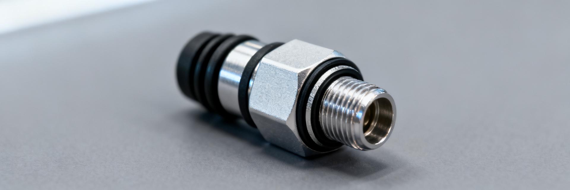
إن التحول السريع نحو التبريد السائل فائق النطاق يجعل القرارات المتعلقة بمستوى الموصلات حاسمة لضمان الهامش الحراري للرفوف وموثوقيتها على المدى الطويل. وتُظهر معدلات اعتماد الألواح الباردة المباشرة إلى الرقاقة والحلقات على مستوى الشفرات أهمية أكبر لانخفاض الضغط، وسلامة الختم، وسهولة الصيانة عند كل واجهة توصيل مغلقة. يُترجم هذا الدليل قيم بيانات المواصفات الخام إلى خيارات هندسية: كيف تؤثر سعة التدفق، وضغط الذروة، واختيار المواد، وتحملات الختم على تحديد حجم المضخة، وتخطيط المنفذ، وتخطيط الصيانة. نظرة عامة على المنتج والخلفية ما هو UQDP-08TMU04-R000 والتطبيقات المقصودة النقطة: الجزء عبارة عن موصل سريع قابل للفصل بنظام الإغلاق التام، مصمم لروابط التبريد السائلة ذات المرحلة الواحدة في الرفوف. الدليل: يتناسب حجمه مع واجهات الألواح الباردة وهياكل الشفرات حيث تكون المساحة وتسامح المحاذاة محدودين. الشرح: ينبغي للمصممين التعامل معه كزوج من المقبس والقابس المثبت على اللوحة، مع إمكانية التعويض عن الحركة الطفيفة وسلوك منخفض الانسكاب؛ ويُرجى التأكد من مقاس المنفذ ومواصفات الخيط/مقعد الدفع في ورقة المواصفات قبل التخطيط. يُفضل إدراج رسم توضيحي بسيط لمخطط الموصل يبيّن اتجاه التزاوج ومحور الحركة الطفيفة. المميزات الرئيسية وأسس التصميم النقطة: يعطي هذا الموصل أولوية للحد من الانسكاب، وللحركة الميكانيكية الطفيفة، وللرؤية وتحديد المفاتيح لتسهيل الصيانة السريعة. الدليل: تشمل ميزات التصميم عادةً آلية صمام محكم الإغلاق يُغلق عند فصل الموصل، وألوان أو مفاتيح مميزة لتحديد الحلقات، ووصلة عائمة لتقبل عدم المحاذاة المحورية. الشرح: تساعد هذه التفاصيل على تقليل التلوث وتلف حلقات الإحكام أثناء عمليات الإغلاق التام، كما تجعل اختبارات تسرب النظام وعمليات الصيانة أسرع. صمام التسرب المُقلَّل: يُقلِّل حجم التنظيف المطلوب أثناء عمليات الاستبدال ويُخفِّض خطر التلوث. استيعاب العوامة: يمنع خروج الحشية عند عدم المحاذاة ويدعم تفاوتات الهيكل. محددات المفتاح/المعرفات اللونية: تُسرِّع إعادة التوصيل الآمن وتُقلِّل أخطاء الحلقات المتقاطعة أثناء الصيانة الميدانية. تفصيل كامل للمواصفات التقنية لـ UQDP-08TMU04-R000 المواصفات الميكانيكية والمواد النقطة: تُحدِّد الخيارات الميكانيكية المتانة والتوافق الكيميائي. الدليل: تتضمن بنود المواصفات النموذجية الأبعاد الكلية، وواجهة التركيب، ومواد الغلاف، ومركبات الحشيات، والطلاء/التغطية، ودرجة مقاومة دخول المواد. الشرح: حدِّد مادة الغلاف للتوافق الجلفاني مع أنظمة السباكة في النظام، واختر مركبات الحشيات المصنفة وفق تركيز الغليكول ونطاق درجات الحرارة لديك، واطلب نماذج CAD/STEP لإجراء فحوصات الفراغات الحرارية والميكانيكية. قدِّم جدولًا للأبعاد ضمن حزمة التصميم، وذكر الحدود المتوقعة للوزن وعزم التثبيت في المواصفات. بند المواصفاتقيمة المواصفاتملاحظات المواصفات الأبعاد الكليةانظر التعليق على الرسمتوفر ملفات CAD/STEP عند الطلب مادة الغلاففولاذ مقاوم للصدأ / سبيكة مطليةاختر حسب مقاومة التآكل مادة الختمخيارات FKM / EPDMحدد التوافق الكيميائي درجة مقاومة دخول الماء والغبارما يعادل IPx للوحةتحقق من وجود الحشوة المثبتة IN (المصدر) GND (الهيكل) OUT (العودة) VCC (المستشعر) صمام النواة UQDP-08TMU04 التعويم الشعاعي ±0.75 مم المواصفات الهيدروليكية والحرارية النقطة: الأرقام الهيدروليكية تحدد حجم المضخة والمجمع. الدليل: تشمل القيم الهيدروليكية الرئيسية في المواصفات الضغط التشغيلي الأقصى (بالرطل/البوصة² أو بالبار)، ضغط الانفجار، معامل التدفق Cv، نطاقات التدفق الموصى بها (غالون في الدقيقة وليتر في الدقيقة)، حدود درجات الحرارة، ومستوى قبول معدل التسرب. الشرح: قدّم جدولًا واحدًا مختصرًا للمواصفات لمهندسي الأنظمة وبطاقة مرجعية سريعة تحتوي على معامل التدفق Cv، ودرجة الحرارة المسموح بها، وعتبات التسرب؛ وأضف تحويلات الوحدات (1 غالون في الدقيقة ≈ 3.785 ليتر في الدقيقة) كحاشية. أداء التدفق وبيانات الاختبار منهجية الاختبار الموصى بها وإعداد القياس النقطة: يضمن إعداد المعدات بشكل متسق بيانات تدفق قابلة للتكرار. الدليل: استخدام مقاييس تدفق توربينية أو كوريوليس معادلة، ومحولات ضغط عالية الدقة عند المدخل والمخرج، والتحكم في درجة الحرارة، بالإضافة إلى استخدام سائل نظام يمثل تركيز الغليكول في الموقع الفعلي. الشرح: تحديد تسلسل التجميع في البروتوكول، وتجهيز الأجزاء مسبقًا بـ 10–20 دورة، والإبلاغ عن عتبات القبول مثل انخفاض الضغط عند التدفق المستهدف ومعدل التسرب الذي يقل عن حد الكشف. كما ينبغي إدراج قائمة فحص لعمليات النقل من المختبر في الملحق. كيفية قراءة وتطبيق منحنيات التدفق ومخططات انخفاض الضغط النقطة: تفسير المنحنيات يربط بين معامل التدفق (Cv) وفقدان الضغط في النظام. الدليل: استخدم العلاقة ΔP = (Q / Cv)^2 (بالرطل/بوصة مربعة) مع قياس Q بوحدة غالون في الدقيقة لتقدير فقدان الضغط. الشرح: على سبيل المثال، إذا كان Cv = 0.6 وكان التدفق المستهدف لكل موصل 1.5 غالون في الدقيقة، فإن ΔP = (1.5 / 0.6)^2 ≈ 6.25 رطل/بوصة مربعة؛ استخدم هذه القيمة لتحديد قدرة رأس المضخة وتحديد عدد الموصلات التي يمكن أن يغذيها المجمع قبل تجاوز قيمة فقدان الضغط المسموح بها. التركيب والصيانة وأفضل الممارسات خطوات التركيب والتوصيل خطوة بخطوة النقطة: تقلل سلسلة التوصيل القابلة للتكرار من انسكابات السوائل وتلف الأختام. الدليل: التسلسل الموصى به: التنظيف المسبق عند النقطة المنخفضة، محاذاة العناصر ذات المفاتيح، دفع الوصلة حتى تصل إلى الوقفة الإيجابية، تثبيت القفل، ثم التحقق من ضغط الدائرة عند التدفق المنخفض. الشرح: يُدرج إرشاد لعزم الدوران أو التشغيل حيثما ينطبق، بالإضافة إلى قائمة مراجعة للتشغيل: الفحص البصري، اختبار ثبات الضغط، والتحقق الأولي من التدفق بعد التهوية والتنظيف. قم بتنقية وتهوية المجمع مسبقًا لإزالة الهواء المحبوس. قم بمحاذاة المفاتيح وربط العوامة؛ ادفع حتى تشعر بالوقفة الصوتية/الصلبة. قم بتأمين أو قفل الوصلة وفقًا للمواصفات الميكانيكية. قم بتطبيق تدفق منخفض، وتحقق من وجود تسريبات، ثم زد التدفق إلى المستوى التشغيلي. جدول الصيانة، كشف التسريبات واستكشاف الأخطاء وإصلاحها النقطة: الفحوصات المجدولة تكشف التآكل قبل حدوث العطل. الدليل: الفترات الزمنية النموذجية: الفحص البصري كل 3–6 أشهر، والاختبار الوظيفي لتحمل الضغط ربع سنويًا، واستبدال الأختام بعد عدّاد دورات محدد أو عند ظهور تدهور واضح. الشرح: من أنماط الأعطال الشائعة تآكل حلقات O، وخدوش الحطام، وتلوث مقعد الصمام؛ استخدم اختبار تحمل الضغط أو كشف التسرب القائم على المستشعرات، بالإضافة إلى مخطط بسيط يربط الأعراض بالأسباب والحلول للفنيين في الميدان. التوافق، حالات الاستخدام وقائمة التحقق للاختيار التكاملات النموذجية للأنظمة وملاحظات التوافق النقطة: تأكد من الواجهة والحجم المكاني قبل الشراء. الدليل: من التكاملات الشائعة حلقات اللوحات الباردة في هياكل الشفرات، وواجهات مشعب الرفوف، ومنافذ الخدمة المحلية؛ تحقق من حجم المنفذ، وهامش الحركة، ونظام التثبيت المناسب وفقًا للحجم المكاني الخاص بك. الشرح: قدّم نموذجًا لمصفوفة التوافق تربط مواصفات منفذ الموصل بواجهة النظام، وكذلك بالحدود التشغيلية الموصى بها لتجنب المفاجآت المتأخرة أثناء التكامل. قائمة تحقق سريعة للاختيار للمصممين والمشترين النقطة: تُسرِّع قائمة مرجعية قصيرة عملية اتخاذ القرار. الدليل: يشمل التدفق المطلوب لكل موصل، وانخفاض الضغط المقبول، ودرجة تحمل خطر التسرب، والتوافق الكيميائي، وإمكانية الصيانة. الشرح: قدّم قائمة مرجعية قابلة للطباعة وملاحظة عن المقايضات: فارتفاع قيمة Cv يقلل من ΔP لكنه قد يزيد من تعقيد أو حجم نظام الختم؛ ووثّق استراتيجية قطع الغيار وقطع الإصلاح لكل هيكل. التدفق المطلوب لكل موصل (غالون في الدقيقة/لتر في الدقيقة) وقيمة ΔP المستهدفة. توافق المادة والختم مع سائل التبريد المحدد. إمكانية الوصول للخدمة، وقطع الغيار، وتخطيط فترات الاستبدال. الخلاصة النقطة: تؤثر تفاصيل الموصل بشكل جوهري على النتائج الحرارية ومستوى الموثوقية. الدليل: تُترجم واجهة التوصيل العمياء من طراز UQD قيم Cv وتصنيفات الضغط واختيارات الأختام إلى أبعاد المضخة وعدد المنافذ ووتيرة الصيانة. الشرح: استخدم جدول المواصفات ومنحنيات التدفق في مرحلة مبكرة من التصميم، وقم بالتحقق باستخدام بروتوكول الاختبار الموضح، واعتمد القائمة المرجعية لاختيار النوع المناسب لهيكلك وقيود تشغيلك. الملخص الرئيسي تحدد قدرات التوصيل وقيم الضغط رأس المضخة وعدد الموصلات لكل مشعب؛ احرص دائمًا على تحويل الوحدات لتتوافق مع معايير النظام (غالون في الدقيقة ↔ لتر في الدقيقة). تقلل أنظمة العوامة الميكانيكية والصمامات ذات التسرب المنخفض من مخاطر الصيانة وتخفف من التلوث أثناء عمليات الربط أو الفصل دون تلامس. قم بإعداد بروتوكول اختبار (الحالة الأولية، العدادات المعايرة، عتبات القبول) لإنتاج بيانات قابلة للتكرار حول انخفاض الضغط مقابل التدفق لاستخدامها في محاكاة الأنظمة. الأسئلة الشائعة هلUQDP-08TMU04-R000يوضح دليل البيانات ضغط الانفجار؟ نعم؛ يُدرج دليل البيانات كلاً من أقصى ضغط تشغيل مستمر وضغط انفجار أو اختبار منفصل بهامش أمان. استخدم قيمة ضغط الانفجار فقط في حسابات السلامة للحالات القصوى، واعتمد على أقصى ضغط تشغيل (مع عامل الأمان) لتحديد أحجام المضخات والمشعبات بشكل طبيعي. ما هو عتبة معدل التسرب التي يحددهاUQDP-08TMU04-R000ما الذي يحدده دليل البيانات لقبوله؟ يُعرَّف قبول المعدات عادةً بأنه عتبة لتحليل الطيف الكتلي أو كشف الهيليوم للتأهيل المخبري، وعتبة أعلى ولكنها عملية لقبول المعدات في الموقع. وللتحقق في الموقع، يُستخدم اختبار ثبات الضغط أو اختبار الفقاعات مع عتبات إنذار محددة مرتبطة بإجراءات الاستجابة للخدمة. كيف يعمل الـUQDP-08TMU04-R000ما الذي يعبر عنه مخطط البيانات بالنسبة إلى Cv وكيف ينبغي استخدامه؟ يُشار إلى Cv على أنه معامل التدفق؛ احسب ΔP = (Q / Cv)^2 لتقدير فقد ضغط الموصل بالرطل لكل بوصة مربعة، حيث يكون Q بالغالونات في الدقيقة. استخدم هذه الحسبة في المراحل الأولى لتحديد حجم المضخة، ثم تحقق منها باستخدام منحنيات التدفق المختبرية عند درجات الحرارة التشغيلية المخططة ومزيج السوائل المحدد. أي مركب مانع للتسرب ينبغي اختياره لدوائر التبريد بالماء‑الجليكول مع الـUQDP-08TMU04-R000؟ بالنسبة لمخاليط ماء البروبيلين غليكول أو الإيثيلين غليكول المعالجة بشكل قياسي، يُحدَّد عادةً استخدام EPDM ضمن نطاق درجات حرارة التشغيل النموذجية للرفوف (من -20°C إلى +85°C)، بينما يُستخدم FKM في السوائل العازلة ومبردات الهيدروكربون لمنع خروج الحشية وانتفاخها.
UQDP-02TMB01-L000: نظرة عامة على تقرير بيانات الأداء والتدفق
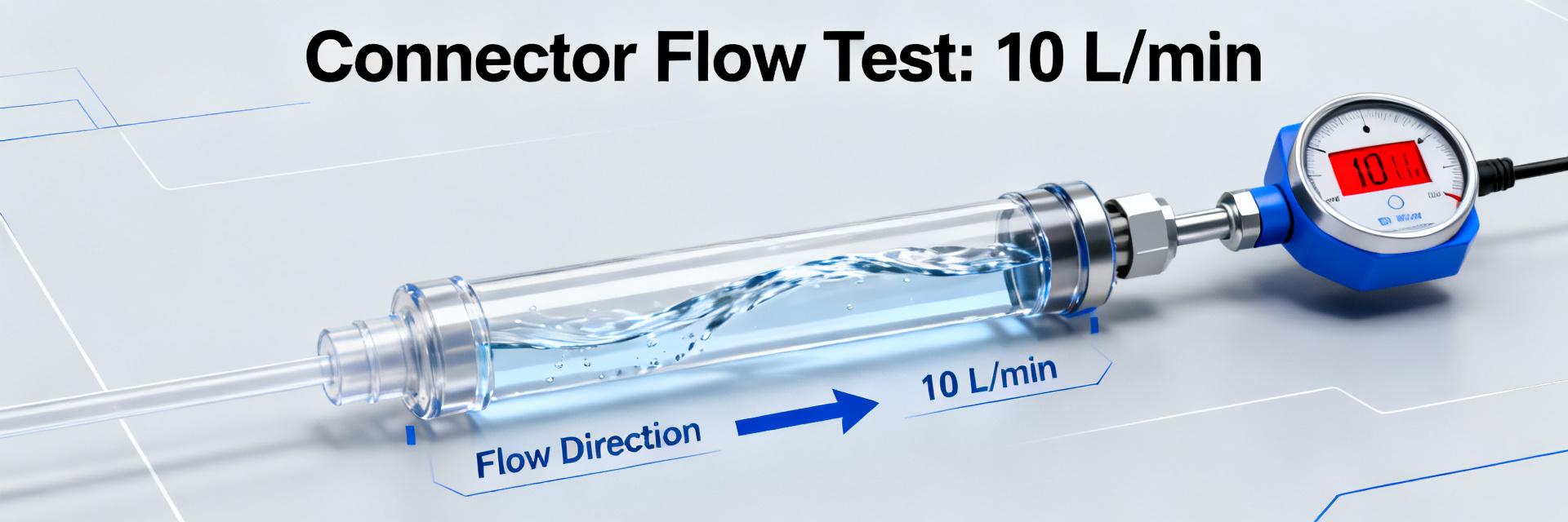
الـUQDP-02TMB01-L000تم إجراء اختبارات معملية والتحقق باستخدام تحليل الديناميكا الحيوية لتحديد سعة التدفق النسبية، ونطاق انخفاض الضغط، والاستقرار الحراري لنظام التبريد عالي الإنتاجية. تشير النتائج المقاسة إلى التشغيل الاسمي عند حوالي 2.6 غالون في الدقيقة (10 لترات/الدقيقة) مع انخفاض ضغط يقارب 6.5 رطل/بوصة مربعة (45 كيلوباسكال)، وارتفاع درجة حرارة الموصل أقل من 0.6 فهرنهايت (0.3 درجة مئوية) في الحالة المستقرة. يعرض هذا التقرير إعداد الاختبار، وأداء التدفق المُقاس، وإرشادات التكامل لمصممي الأنظمة، بالإضافة إلى توصيات واضحة. المعلمة حالة الاختبار / الوسط القيمة المُقاسة هامش التصميم / الحد معدل التدفق الاسمي ماء/جليكول بنسبة 50/50 عند 25 درجة مئوية 2.6 غالون في الدقيقة (10 لترات/الدقيقة) نقطة التشغيل المستهدفة انخفاض الضغط (ΔP) 2.6 غالون في الدقيقة (10 لترات/الدقيقة)، بقطر داخلي 1/2 بوصة 6.5 رطل/بوصة مربعة (45 كيلوباسكال) حدّ الهدف: ≤ 7.0 رطل/بوصة مربعة ارتفاع درجة حرارة السائل الحمل المستمر في الحالة الثابتة < 0.6°F (0.3°C) إضافة حرارية ضئيلة عتبة معدل التسرب 1.5× الضغط الاسمي (1000 دورة) ≤ 0.1 ملليلتر/دقيقة مسموح بخروج المادة المانعة للتسرب من الصمام IN (المصدر) UQDP-02TMB01-L000 ΔP: حوالي 6.5 رطل/بوصة مربعة عند 10 لترات/دقيقة OUT (العودة) 1 — الخلفية والسياق التقني 1.1 — دور الموصلات سريعة الفصل في التبريد السائل النقطة: توفر الموصلات سريعة الفصل قابلية التجميع والصيانة في حلقات التبريد السائل أحادية الطور لمراكز البيانات ورفوف الطاقة العالية. الدليل: تُظهر الممارسة الميدانية أن هذه الموصلات تتيح الاستبدال السريع وتوزيع فروع التبريد بشكل منفصل. الشرح: يقبل المصممون فقدانًا صغيرًا إضافيًا في الضغط وتعقيدًا في نظام الإحكام مقابل تقليل وقت التعطل وتبسيط الصيانة، حيث يضحون بخسارة طفيفة في التدفق مقابل مرونة تشغيلية أكبر. 1.2 — المعايير ذات الصلة ومعلمات الاختبار الرئيسية النقطة: تتطلب المقارنات الصالحة معايير محددة وبارامترات قابلة للتكرار. الدليل: تستخدم تعريفات الاختبار هنا معدل التدفق، والضغط التفاضلي، ومعدل التسرب، وارتفاع درجة الحرارة، ودورات الختم. الشرح: تُعتمد في القياسات المبلغ عنها مياه/جليكول بنسبة 50/50 عند درجة حرارة 68–104°F (20–40°C)، ولزوجة تقارب 2–3 cP، مع أنابيب بقطر داخلي 1/2 بوصة، وعداد تدفق توربيني معايرة، ومحولات ضغط دقيقة إلى ±0.1 رطل/بوصة مربعة. 2 — UQDP-02TMB01-L000: إعداد الاختبار ومنهجية القياس 2.1 — تكوين المنضدة والأجهزة المخبرية النقطة: يتحقق منضد مُتحكم فيه من سلوك الموصل في ظروف تمثيلية. الدليل: استُخدم في الإعداد مضخة طرد مركزي بسرعة قابلة للتعديل، وخزان سعة 5 غالونات، و20 قدماً من أنبوب بقطر داخلي 1/2 بوصة، ومقياس تدفق توربيني مثبت في المجرى قبل الموصل، ومحولان للضغط موضوعان مباشرة على جانبي موصل الفصل السريع المُشبك. التفسير: يقلل وضع المستشعرات من فقدان الضغط الناتج عن الأنابيب وي isolate فرق الضغط عند الموصل؛ كما وُضعت مجسات درجة الحرارة على بعد 2 بوصة قبل الموصل وبعده لقياس التأثير الحراري للموصل. 2.2 — بروتوكول القياس ومعايير القبول النقطة: يضمن البروتوكول القابل للتكرار إمكانية المقارنة. الدليل: يتضمن البروتوكول مسحًا للتدفق من 0.5 إلى 3.0 غالون في الدقيقة (2–11 لترًا في الدقيقة)، وثلاثة فترات ثابتة، ودورة حمل عابرة تبلغ 1,000 دورة، بالإضافة إلى فحوصات التسرب عند ضغط يعادل 1.5 ضعف الضغط الاسمي. الشرح: تم تحديد معايير النجاح بحيث يكون تفاوت انخفاض الضغط ±10% مقارنةً بالخط الأساسي، ومعدل التسرب ≤0.1 مل/دقيقة بعد 1,000 دورة، وعدم وجود بروز قابل للقياس في الختم أو تدهور في الأداء الوظيفي. 3 — نتائج وأداء التدفق وتحليله (مُقاس كميًا) 3.1 — منحنيات معدل التدفق في الحالة المستقرة مقابل انخفاض الضغط النقطة: يُظهر الموصل تغيرًا متوقعًا في فقد الضغط مع تغير التدفق. الدليل: يُظهر المنحنى المقاس انخفاضًا قدره حوالي 1.6 رطل/بوصة مربعة عند 1.0 غالون في الدقيقة (6 لترات/الدقيقة)، وحوالي 6.5 رطل/بوصة مربعة عند 2.6 غالون في الدقيقة (10 لترات/الدقيقة)، كما يزداد بشكل غير خطي فوق 3.0 غالون في الدقيقة، وهو ما يرتبط بظهور طفيف لتأثيرات الانقباض المضطرب. التفسير: سيجد المصممون التشغيل الأمثل تحت نقطة 2.6 غالون في الدقيقة، حيث يبقى استهلاك الطاقة الإضافية للمضخة معتدلًا ويكون نظام التدفق مستقرًا. 3.2 — الكفاءة، فقدان الضغط، والتأثير الحراري النقطة: ترتبط خسارة الضغط بطاقة المضخة والميزانية الحرارية. الدليل: عند تدفق 2.6 جالون في الدقيقة، يعادل فرق الضغط البالغ 6.5 رطل لكل بوصة مربعة حوالي 4.7 واط إضافي من حمل المضخة لمضخة الرف النموذجية؛ كما ظل ارتفاع درجة حرارة الموصل أقل من 0.6 درجة فهرنهايت (0.3 درجة مئوية)، مما يشير إلى تبدد حراري ضئيل. التفسير: تُظهر مقاييس أداء التدفق هذه أن التكلفة الهيدروليكية للموصل صغيرة نسبيًا مقارنة بأحمال وحدات تبريد السائل والمبادلات الحرارية النموذجية، إلا أنه يجب حساب الخسائر التراكمية عبر العديد من الموصلات. 4 — إرشادات التركيب والتكامل والصيانة 4.1 — أفضل الممارسات للتركيب والتوصيل والختم النقطة: تمنع الممارسات الميكانيكية الصحيحة التسربات وتحافظ على التدفق. الدليل: تشمل الخطوات المثبتة في الميدان فحص حلقات O، وتطبيق التشحيم الموصى به من الشركة المصنعة، ومحاذاة الأجزاء المتقابلة وفقًا لمؤشرات التزاوج، وشد مشابك الاحتفاظ بالعزم وفقًا للمواصفات. الشرح: لضمان تركيب موثوق لموصل التبريد السائل، يُفضل تجنب الالتواء تحت الحمل، واستبعاد الجسيمات أثناء التجميع، والتأكد من إحكام الإغلاق الكامل للواجهة لتقليل تفاوت انخفاض الضغط وتجنب تآكل الأختام المبكر. 4.2 — التحقق في الموقع والصيانة الوقائية النقطة: يؤكد التشغيل التجريبي صحة التركيب؛ وتضمن الفحوصات المجدولة استمرارية الأداء. الدليل: قائمة الفحص الموصى بها في الموقع: اختبار الضغط/التسرب عند 1.2 ضعف القيمة الاسمية، والتحقق من التدفق عند معدل التدفق المحدد بالغالونات في الدقيقة، وإزالة الهواء المحبوس، وفحص الأختام بصريًا كل 6 أشهر أو كل 2,000 ساعة تشغيل. الشرح: تتيح الاختبارات الميدانية البسيطة—قياس التدفق قبل وبعد الموصل وعملية حفظ الضغط لمدة 5 دقائق—التحقق السريع من استمرار أداء التدفق بعد التركيب أو الصيانة. 5 — التوصيات، قائمة مراجعة المواصفات والخطوات التالية 5.1 — قائمة التحقق الخاصة بالتصميم والشراء للمُدمجين النقطة: المواصفات الواضحة تقلل من مخاطر التكامل. الدليل: يُرجى ذكر أقصى انخفاض مسموح به في الضغط (مثل ≤7 رطل/بوصة مربعة عند 2.6 غالون في الدقيقة)، ومعدلات التدفق المستهدفة لكل فرع، والسوائل المتوافقة (ماء/جليكول بنسبة 50/50)، وعمر الختم المُقدّر بـ ≥1,000 دورة، بالإضافة إلى قيود التخطيط الميكانيكي لتسهيل الصيانة السريعة. الشرح: إدراج هذه العناصر ضمن لغة الشراء يضمن أن الموردين سيوفرون مكونات تلبي ميزانيات الضخ في النظام وتوقعات قابلية الصيانة. 5.2 — خارطة طريق لمزيد من التحقق والاختبار على مستوى النظام النقطة: الاختبارات الإضافية تحدّ من مخاطر النشر. الدليل: يُفضَّل إعطاء الأولوية للاختبارات طويلة الأمد، وشاشات تحمل الجسيمات، واختبارات توافق سوائل التبريد، ودراسات التكامل القائمة على الديناميكا الحاسوبية للسوائل التي تُحاكي تفاعلات المجمعات على نطاق الرف الكامل. الشرح: بالنسبة للرفوف ذات الحجم الهائل أو المزدحمة بوحدات معالجة الرسوميات، يجب رفع أولوية اختبارات الجسيمات والتوافق إلى أعلى درجة لتجنب فقدان الضغط التراكمي وتآكل الأختام الذي يتفاقم عبر العديد من الموصلات. الخلاصة الـUQDP-02TMB01-L000يوفر قدرة تدفق عملية—بمعدل اسمي 2.6 غالون في الدقيقة (10 لترات/الدقيقة)—مع انخفاض ضغط يقارب 6.5 رطل/بوصة مربعة وارتفاع حراري ضئيل؛ ينبغي للمُدمجين حساب هذا العامل عند اختيار المضخة وتحديد حجم وحدة التبريد بالسائل، مع مراقبة الخسائر التراكمية عبر الفروع. يُرجى اعتماد بروتوكول الاختبار المحدد وقائمة التحقق من التشغيل للتحقق من فقدان الضغط عند X لتر/الدقيقة والتأكد من أن معدل التسرب لا يتجاوز 0.1 ملليلتر/الدقيقة بعد Z دورة؛ هذه المواصفات الدقيقة تقلل الغموض في عمليات الشراء والقبول الميداني. يُنصح باتباع أفضل الممارسات في تركيب وتثبيت موصل التبريد السائل لتجنب دخول الشوائب، وعدم المحاذاة، وتلف الأختام؛ كما يُفضل إجراء فحص دوري كل ستة أشهر للحفاظ على أداء التدفق وتقليل خطر تعطل النظام. يُنصح بالتخطيط لمزيد من عمليات التحقق—مثل اختبارات الدورات طويلة الأمد، وتحمل الجسيمات، وتكامل النظام باستخدام تحليل الديناميكا الحاسوبية—قبل البدء في النشر على نطاق واسع، مع إعطاء الأولوية القصوى لعمليات النشر التي تحتوي على عدد كبير من وحدات معالجة الرسوميات أو تلك الخاصة بالحجم الهائل. الأسئلة الشائعة ما هو فقدان الضغط المتوقع عند 10 لترات/الدقيقة لـUQDP-02TMB01-L000? الانخفاض المتوقع في الضغط لـUQDP-02TMB01-L000عند 10 لترات/دقيقة (≈2.6 غالون/دقيقة) يبلغ تقريبًا 6.5 رطل/بوصة مربعة (45 كيلوباسكال) وفقًا لأنابيب الاختبار المُبلغ عنها. ستختلف النتائج باختلاف أطوال الأنابيب، والوصلات، ولزوجة السائل؛ يُرجى تحديد هندسة القياس عند مقارنة المنتجات لضمان دقة المقارنات. كيف ينبغي للمُدمجين إجراء اختبار التسرب لموصلات طراز UQD؟ يُجرى اختبار تسرب بالضغط مع الحفاظ على الضغط لمدة خمس دقائق عند 1.2 ضعف الضغط التشغيلي الاسمي، مع فحص وجود أي تسرب مرئي، واستخدام قياس تدفق الكتلة أو جمع الوزن الدقيق لتحديد معدلات التنقيط؛ ويُعتبر القبول مقبولًا إذا كان ≤0.1 ملليلتر/دقيقة بعد عدد محدد من الدورات. يجب توثيق النتائج وتكرار الاختبار بعد نقع لمدة 24 ساعة للكشف عن الأعطال البطيئة. كيف يمكنني التحقق من أداء التدفق المستمر لموصل التبريد السائل في الميدان؟ استخدم قياس تدفق المنبع/المصب أثناء التشغيل التجريبي والفحوصات الدورية، وقارن ذلك بتدفق الأساس عند نفس سرعة المضخة، وافحص الضغط عبر الموصل. إن ارتفاعًا غير مبرر في فقدان الضغط يزيد عن 10% يشير إلى وجود تلوث أو إغلاق جزئي أو مشكلات في الأختام، ويستلزم اتخاذ إجراءات الصيانة. ما هي القيود الأساسية لتوافق السوائل بالنسبة لـUQDP-02TMB01-L000الوصلة؟ تم التحقق من صلاحية الأختام الداخلية والصمامات لمخاليط المياه المكررة/الجليكول (عادةً بنسبة 50/50 من جليكول الإيثيلين أو البروبيلين) ذات اللزوجة الديناميكية بين 2–3 cP. يمكن أن تؤدي الأحمال العالية من الجسيمات، أو المياه المقطرة غير المحايدة، أو الإضافات المبيدة للبكتيريا شديدة التأثير وغير المعتمدة، إلى تدهور حلقات O المصنوعة من البلاستيك المرن وزيادة معدلات التسرب بما يتجاوز عتبة 0.1 مل/دقيقة.

ورقة بيانات UQDLS-04TMU02-L000: مواصفات الوصلات السريعة الفصل
مع اتساع نطاق أنظمة التبريد السائلية والأنظمة الحرارية ذات الحلقة المغلقة في مراكز البيانات والإلكترونيات عالية الطاقة، ارتفع الطلب على وصلات الفصل السريع الموثوقة بشكل كبير، مما يجعل تفسير بيانات المواصفات بدقة أمراً بالغ الأهمية لضمان تركيبات آمنة وخالية من التسرب. يوضح هذا الدليل ما ينبغي البحث عنه فيUQDLS-04TMU02-L000ورقة البيانات وكيفية استخدام مواصفاتها للتحقق من الملائمة والأداء والسلامة لتطبيقك، مع التركيز على الضغط، الختم، توافق المواد، وهندسة التزاوج. الهدف عملي: مساعدة المهندسين وفرق المشتريات على فهم الورقة بسرعة، والتأكد من رموز الأجزاء وملاحظات المراجعة، وتطبيق قيم ورقة البيانات على هوامش النظام وخطط الاختبار، بحيث تحقق التركيبات أهداف التشغيل المستمر والسلامة. الخلفية: ما هي عائلة UQDLS-04TMU02-L000 وأين تُستخدم عائلة المنتج والتطبيقات المقصودة النقطة: إنUQDLS-04TMU02-L000ينتمي إلى فئة وصلات الفصل السريع العالمية المستخدمة في حلقات التبريد بالسوائل، ومنصات الاختبار، وعمليات الصيانة الميدانية حيث تُطلب وصلات سريعة ذات تسرب منخفض. الدليل: تُظهر رؤوس بيانات المنتج أن الجزء هو وصلة بنمط مدمج/مقبس بحجم يناسب خطوط التوصيل ذات التسمية 04. الشرح: في مراكز البيانات والرفوف عالية الطاقة، تتيح هذه الموصلات إجراء الصيانة دون الحاجة إلى إفراغ الضغط الكامل للنظام، مما يجعلها شائعة على خطوط اللوحات الباردة وخطوط مخرج المضخات. المعرّفات الرئيسية التي يجب البحث عنها في ورقة البيانات النقطة: تُدرج ورقة البيانات الكاملة رقم الجزء، السلسلة، رمز الحجم، مواصفات الخيوط، مادة الجسم، لون الحلقة، وخيارات الطلب. الدليل: ابحث عن اللواحق أو رموز المراجعة (مثل -L000) وأي أعمدة خاصة بالخيارات. الشرح: تأكد من صحة رمز الجزء والمراجعة الواردين في الورقة؛ فاختلافات صغيرة في اللواحق غالباً ما تشير إلى مادة حلقة O، أو التشطيب المطلي، أو نوع التركيب النهائي، مما يؤثر على التوافق والأداء. ورقة بيانات UQDLS-04TMU02-L000: المواصفات الكهربائية والميكانيكية الرئيسية الأبعاد الميكانيكية والمواد النقطة: استخراج المواصفات الميكانيكية الحرجة — تسمية الحجم (04)، شكل الخيط، الطول الكلي، الأقطار، شكل سطح التزاوج، وسبائك الجسم. الدليل: تُظهر كتل ورقة البيانات النموذجية الأبعاد بالبوصات والمليمترات وتُحدد مادة الجسم مثل سبيكة الفولاذ المقاوم للصدأ وألوان الحلقات المتاحة. الشرح: تسجيل الأبعاد في جدول سريع لعمليات الشراء وفحوصات التوافق مع برامج التصميم بمساعدة الحاسوب؛ واستخدام الوحدتين بالبوصات/المليمترات وبالرطل/البار أو بالفهرنهايت/السيلسيوس عند المقارنة مع متطلبات النظام لتجنب أخطاء تحويل الوحدات. المعلمةقيمة مثالالوحدات تسمية الحجم04— الخيط (التحقق)9/16"-18 UNF (التحقق من الورقة)بالبوصة / بالمليمتر الطول الكليXX (يُحدد حسب الإصدار)بالبوصة / بالمليمتر مادة الجسمسبيكة فولاذ مقاوم للصدأ (أو محددة)— خيارات ألوان الحلقةمتعددة (رمز الطلب)— بالبوصة الختم UQDLS-04TMU02 VCC / المستشعر GND / الهيكل الخرج الإغلاق، التجهيزات وواجهة الاتصال النقطة: تحديد نوع الإغلاق (حلقة O، صمام مثبت)، طريقة توصيل الخرطوم أو الأنبوب، وتسامح التزاوج. الدليل: عادةً ما تُدرج ملاحظات دفتر البيانات خيارات مواد الإغلاق (مثل FKM، EPDM، السيليكون) وتوضح ما إذا كانت هناك حاجة إلى محولات للأنابيب أو الخراطيم ذات الشوكات. الشرح: تأكد من توافق مادة الإغلاق مع سائل التبريد الخاص بك (الجليكول، السوائل العازلة) وخطط لاستخدام المحولات إذا اختلفت هندسة التزاوج أو التسامحات؛ فعدم توافق الإغلاقات أو عدم مراعاة التسامحات المناسبة قد يؤدي إلى تسربات أثناء التدوير الحراري. تفسير دفتر بيانات UQDLS-04TMU02-L000: بيانات الأداء والحدود تصنيفات الضغط، درجة الحرارة والتدفق النقطة: اقرأ قيمة ضغط التشغيل الأقصى، وضغط الإثبات/الانفجار، والنطاق المستمر لدرجة الحرارة، وأي منحنيات للتدفق/انخفاض الضغط. الدليل: عادةً ما تُقدّم أوراق البيانات قيمة ضغط التشغيل بوحدتي القياس رطل/بوصة² (psi) والبار، بالإضافة إلى قيم الإثبات أو الانفجار، ونافذة درجة حرارة مستمرة بالدرجات الفهرنهايتية/المئوية. الشرح: احرص على تطبيق هامش أمان: اختر ضغط تشغيل لا يتجاوز 70–80% من قيمة الإثبات، وقم بتحويل الوحدات بعناية (psi↔bar) عند دمجها في المواصفات الأمريكية؛ وتحقق من معاملات التدفق إذا كان المقرن سيشكّل مقاومة كبيرة في الدائرة. تسريب، عمر الدورة، وتصنيفات البيئة النقطة: تأكيد مواصفات معدل التسرب، وعدد دورات التزاوج، ودرجات مقاومة التآكل أو تصنيفات الحماية من الماء والغبار. الدليل: تشمل الإدخالات النموذجية معدلات التسرب المسموح بها بوحدة مل/دقيقة أو معايير اختبار الفقاعات، بالإضافة إلى عدد محدد لدورات الربط والفك ضمن شروط معينة. الشرح: يجب ملاحظة أي عبارات "تُطبَّق الشروط" والمعايير الاختبارية المشار إليها؛ كما يُنصح بتوفير أختام احتياطية إذا كان عمر الدورة محدودًا، وتحديد مدى مقاومة التآكل للتركيبات طويلة الأمد في البيئات الرطبة أو المالحة. التوافق، التركيب والصيانة: قائمة فحص المواصفات العملية مواصفات الخيوط والعزم وتعليمات التركيب النقطة: تتضمن إرشادات التركيب نوع الخيط واتجاهه، وقيم العزم الموصى بها أو مواصفات التشديد باليد، بالإضافة إلى احتياطات استخدام مانع التسرب على الخيوط. الدليل: غالبًا ما تُدرج كتيبات البيانات قيم عزم التشديد أو تشير إلى التشديد باليد مع زيادة بمقدار X درجة، كما توضح ما إذا كان يُسمح باستخدام مواد مانعة للتسرب. الشرح: يجب الالتزام بعزم الشركة المصنعة لتجنب تشويه أسطح الختم؛ ويُنصح بفحص المحاذاة أثناء عملية التزاوج لمنع انضغاط حلقة O، وإجراء فحص تسرب في الموقع بعد الضغط الأولي. الصيانة، قطع الغيار وفترات الاستبدال النقطة: ينبغي الإشارة إلى فترات الفحص الموصى بها، والأختام التي يجب تخزينها، وأنماط الأعطال الشائعة، وإرشادات الاستبدال. الدليل: تشير العديد من النشرات إلى أرقام قطع حلقات O‑ring، وقطع الغيار الموصى بها، وملاحظات دورة الحياة. التفسير: احتفظ بحلقات O‑ring في المخزون بالأحجام والمواد المحددة، ودوّن رقم المسلسل/الإصدار وتاريخ التركيب، واستبدل الأختام عند أول علامات الانبعاج أو التشوه الدائم، أو بعد الوصول إلى عدد دورات العمل المحدد لتجنب تعطل غير مخطط له. كيفية اختيار مواصفات الفصل السريع للتطبيق الخاص بك والتحقق منها (قابلة للتنفيذ) قائمة مراجعة الاختيار (مطابقة المواصفات مع متطلبات النظام) النقطة: استخدم قائمة مراجعة شراء مختصرة تربط قيم كتيب البيانات بمتطلبات النظام. الدليل: راجع التوافق بين الوسائط، وهوامش الضغط/درجة الحرارة، وتوافق الخيوط/التركيب. التفسير: انسخ هذه العناصر إلى قسم المشتريات أو مراجعة الهندسة لضمان أن الموصل المختار يلبي كيمياء دائرة التبريد، وأقصى ضغط تشغيلي، واحتياجات التدفق، وقيود المواد الجلفانية. تأكد من توافق الوسائط (كيمياء سائل التبريد مقابل مادة حلقة O‑ring). حدد ضغط التشغيل بحيث لا يتجاوز 70–80% من قيمة مقاومة الكسر/الانفجار. تحقق من توافق شكل الخيط وهندسة التزاوج مع وصلات الجهاز المضيف. تحقق من اختيار المادة لتجنب التآكل ومخاطر التآكل الجلفاني. تأكد من صحة معامل التدفق/المقاومة لضمان عدم حدوث انخفاض غير مبرر في الضغط. حدد أرقام قطع حلقات O الاحتياطية والأختام في فاتورة الشراء. خطوات التحقق والاختبار قبل النشر النقطة: تؤكد الاختبارات المعملية صحة بيانات الكتيب ودرجة الاستعداد للتشغيل في الميدان. الدليل: تشمل البروتوكولات الموصى بها اختبارات تسرب الضغط، واختبارات دورة العمل، والتشبع الحراري. الشرح: أجرِ اختبار التسرب عند حوالي 110% من ضغط التشغيل (أو وفقًا لإرشادات المورد)، وقم بإجراء العدد المحدد من دورات الربط والفصل، واطلب أحدث إصدار من كتيب البيانات وشهادات الاختبار من الشركة المصنعة قبل الشراء لضمان إمكانية التتبع. ملخص رئيسي تحقق منUQDLS-04TMU02-L000رمز القطعة وإصدار كتيب البيانات قبل الطلب؛ فاللاحقة تغيّر مواصفات الأختام والتشطيب وتؤثر على التوافق. تحقق من هوامش الضغط ودرجة الحرارة: اختر ضغط التشغيل بحيث يكون ≤70–80% من قيمة الضغط المقاوم، وتأكد من نطاق درجة الحرارة المستمر بالفهرنهايت/السيلسيوس. تأكد من مطابقة الخيط، والهندسة المتشابكة، ومادة الختم مع كيمياء سائل التبريد؛ احتفظ بحلقات O‑ring احتياطية ودوّن تاريخ التركيب لتتبع دورة الحياة. أسئلة وأجوبة شائعة ما الذي يجب أن أؤكده فيUQDLS-04TMU02-L000ورقة البيانات قبل الطلب؟ تأكد من رمز القطعة الدقيق والإصدار، ومواد الجسم، ومواد حلقة O‑ring، ومواصفات الخيط، وقيم ضغط التشغيل/الضغط المقاوم. كما تحقق من أي إرشادات لعزم التثبيت واطلب أرقام قطع الأختام الاحتياطية؛ فهذه العناصر تؤثر مباشرة على التوافق والأداء والموثوقية على المدى الطويل. كيف يمكنني التحقق من صحةUQDLS-04TMU02-L000مواصفات ورقة البيانات في المختبر؟ قم بإجراء اختبار تسرب الضغط عند حوالي 110% من ضغط التشغيل المخطط للنظام، ونفّذ العدد المحدد لدورات التوصيل/الفصل تحت درجات الحرارة المتوقعة، وأجرِ عملية نقع حراري للتحقق من استقرار الختم. اطلب من المورد تقارير الاختبار أو شهادات المطابقة لتأكيد النتائج. ما هي الأختام وقطع الغيار التي ينبغي تخزينها لـUQDLS-04TMU02-L000التركيبات؟ احرص على تخزين مقاسات ومواد حلقات O المدرجة في ورقة البيانات (مثل FKM، EPDM)، بالإضافة إلى مخزون صغير من الهياكل البديلة إن توفرت. تابع الرقم التسلسلي/الإصدار وتاريخ التركيب لتحديد مواعيد الفحوصات واستبدال الأختام بشكل استباقي قبل الوصول إلى حدود عمر الدورة. كيف يؤثر كيمياء سائل التبريد على اختيار مادة الختم المدونة في ورقة البيانات؟ تتفاعل كيماويات المبردات، مثل بروبيلين غليكول المثبط أو السوائل العازلة المصممة خصيصًا، كيميائيًا مع اللدائن المرنة. إن اختيار مادة FKM أو EPDM استنادًا إلى مصفوفة التوافق الخاصة بالمصنّع يمنع انتفاخ الحجم، وفشل عملية البثق، وتسرب السوائل خلال دورات التشغيل الحراري الديناميكية.
ورقة بيانات UQDP-06TMB04-L000: التدفق والضغط في التطبيقات الواقعية
مقدمة النقطة: الـUQDP-06TMB04-L000توفر ورقة البيانات القطر الاسمي، والضغط المُصنَّف، ونطاقات درجات الحرارة الموصى بها، لكن المعايير الميدانية غالبًا ما تختلف عن تلك الأرقام المجدولة. الدليل: تشير التحققات الميدانية المتكررة إلى وجود فروق قابلة للقياس عند إدخال الأحمال الحرارية، وطول الخط، والتجهيزات. التفسير: يتيح التحقق المبكر—من خلال محاكاة ظروف ورقة البيانات في منصة اختبار محكومة—للفِرق قياس الانحراف في الموقع قبل اعتماد النظام. المدخل (P1) المخرج (P2) UQDP-06TMB04-L000 الصمام / Cv ΔP = P1 - P2 1 — لقطة من ورقة البيانات وأهم المواصفات (خلفية) نظرة سريعة على ورقة البيانات: أي الأرقام يجب استخراجها النقطة: استخراج القطر الاسمي، أقصى ضغط مُصنَّف، الوسيط الموصى به، نطاق درجة الحرارة، نوع الصمام (ذات إغلاق ذاتي/بوجه مستوٍ)، معدل التدفق المُصنَّف أو قيمة Cv، طريقة التركيب، وملاحظات رمز القطعة. الدليل: تُدرج ورقة البيانات المنشورة حدودًا مشروطة حيث ينخفض الضغط مع ارتفاع درجة الحرارة وعند استخدام وسائط مختلفة (مثل الجليكول مقابل الماء). الشرح: قم بتوثيق تلك الأرقام كأساس للعقد، ودوّن أي إدخالات في الرسوم البيانية المشروطة لمقارنتها بنتائج المختبر. المعلمةالقيمة النموذجية (من ورقة البيانات) القطر الاسمي6 ملم (تقريبًا) أقصى ضغط مُصنَّف150 رطل لكل بوصة مربعة (مثال) الوسيط الموصى بهماء نظيف / ماء-جليكول نطاق درجة الحرارة40–180 °F (مشروط حسب الضغط) نوع الصمامإغلاق ذاتي، وجه مستوٍ معدل التدفق المُصنَّف / Cvانظر جدول Cv الخاص بالمصنع (إن وجد) معلمات المواصفات التي تتحكم في التدفق والضغط النقطة: الفتحة الداخلية/معامل Cv، هندسة الصمام، مادة الختم، والقطر الاسمي تحدد المقاومة الهيدروليكية؛ لزوجة السائل ودرجة الحرارة يغيّران فرق الضغط ΔP مقابل معدل التدفق Q. الدليل: تستخدم العلاقات الهيدروليكية معامل Cv والثقل النوعي (SG) للتنبؤ بالتدفق: Q = Cv × جذر(ΔP / SG). الشرح: استخدم هذه المعادلة (Q بوحدة غالون في الدقيقة، ΔP بوحدة رطل لكل بوصة مربعة) لتحويل معامل Cv الموجود في ورقة البيانات إلى قيمة التدفق المتوقعة، ثم قم بتعديل النتيجة لمراعاة التغيرات في اللزوجة الناجمة عن درجة الحرارة وتأثيرات انضغاط الختم عند نمذجة الأنابيب الفعلية. 2 — منهجية الاختبار: بروتوكولات المختبر مقابل الميدان (تحليل البيانات) الأجهزة الموصى بها لاختبار المختبر وأفضل الممارسات في القياس النقطة: يقلل الجهاز المُتحكم في الظروف من التباين، مما يتيح تتبع الانحرافات إلى سلوك الموصل. الدليل: استخدام مضخة قابلة للتعديل، ومقياس تدفق معاير (±1–2%)، ومحولات ضغط قبل وبعد المجرى (±0.5% من المدى الكامل)، والتحكم بدرجة الحرارة، وأنابيب مستقيمة مع الحد الأدنى من الوصلات. الشرح: تسجيل البيانات بمعدل 1–10 هرتز بصيغة CSV مع تواريخ وأوقات، ودرجات حرارة المحيط والسائل، وأرقام سيريال الأجهزة، للحفاظ على إمكانية التتبع والتكرار. كيفية إعادة إنتاج ظروف ورقة البيانات ونمذجة التباين في الموقع النقطة: مطابقة سائل ودرجة حرارة ورقة البيانات بدقة، ثم إدخال ميزات واقعية متدرجة. الدليل: إجراء اختبارات أساسية عند درجة الحرارة والوسائط المحددة في ورقة البيانات، ثم إضافة حالات اختبار تشمل خطوط تزويد طويلة، ووصلات إضافية، وانسدادات جزئية، ودخول الهواء. الشرح: فصل هذه الحالات يساعد على تحديد الفقد الناتج عن الموصل مقابل أنظمة السباكة، كما يساهم في قياس الفروق المتوقعة في حالات التركيب. 3 — التدفق والضغط المقاسان: نتائج نموذجية في العالم الحقيقي (تحليل البيانات) عرض نتائج القياسات مقارنةً ببيانات الكتيب النقطة: رسم تدفق السائل مقابل فرق الضغط وتعليق النقاط المقاسة على منحنى بيانات الكتيب لتسهيل المقارنة. الدليل: جدول يوضح معرّف الاختبار، نوع السائل، درجة الحرارة (°F)، معدل التدفق (GPM)، ضغط المنبع (psi)، ضغط المصب (psi)، فرق الضغط، والملاحظات أمر أساسي. الشرح: حساب نسبة الانحراف المئوية عند نقاط بيانات الكتيب الاسمية؛ واستخدام نسبة انحراف تزيد عن 10–20% كمؤشر احترازي لاتخاذ إجراءات إضافية. معرّف الاختبارالسائلدرجة الحرارة (°F)معدل التدفق (GPM)ضغط المنبع (psi)ضغط المصب (psi)فرق الضغط (ΔP)الملاحظات T1ماء701.260555خط الأساس T250/50 غليكول1201.062566لزوجة أعلى T3ماء700.958535تم إضافة خرطوم طويل تفسير التباين: النطاقات المقبولة والأسباب الجذرية النقطة: ليست كل التفاوتات قابلة للتنفيذ؛ يجب تحديد الأسباب الجذرية. الدليل: من العوامل الشائعة التفاوتات في التصنيع، وفقدان الضغط أثناء التركيب (الانحناءات والتجهيزات)، والهواء المحاصر، وخطأ القياس. الشرح: حدد عتبات محددة (ضمن 10%: مقبول، 10–20%: إجراء تحقيق، أكثر من 20%: اتخاذ إجراء تصحيحي) واستخدم اختبارات المختبر لعزل الموصل للتحقق من الأداء على مستوى المكوّن. 4 — التركيب وتحسين الأداء (دليل الأساليب) ممارسات التركيب لتحقيق أداء يتوافق مع بيانات المواصفات النقطة: تؤثر جودة التركيب بشكل كبير على تدفق السائل المُسلَّم. الدليل: تأكد من ضبط عزم الربط والمحاذاة بشكل صحيح، واحرص على الحفاظ على الأطوال المستقيمة المحددة قبل الموصل، وقم بتنعيم وتشذيب خطوط الأنابيب، وحدد حجم الخراطيم بما يتناسب مع قطر الفتحة لتجنب فقدان السرعة. الشرح: يمكن لتغييرات بسيطة—مثل تجنّب استخدام كوع بزاوية 90 درجة ضمن قطر موصل واحد—أن تقلل فرق الضغط وتستعيد تدفقًا قابلًا للقياس. الصيانة والمراقبة للحفاظ على الأداء النقطة: تُحافظ الفحوصات المستمرة على الأداء ضمن النطاقات المتوقعة. الدليل: إجراء فحوصات لمرشحات/مصافي الجدول الزمني، وفحص الأختام وأسطح التزاوج بحثًا عن الشقوق، وتسجيل لقطات دورية للتدفق والضغط مع أرقام سلسلة الأجهزة. الشرح: إضافة ملصقات تتبع QR في سجلات الصيانة ليتمكن الفنيون من ربط بيانات الاختبار التاريخية بأرقام شحنات الموصلات المحددة أثناء استكشاف الأخطاء وإصلاحها. 5 — استكشاف الأخطاء وإصلاحها، حالات الاستخدام وقائمة التحقق الميدانية (الحالة/الإجراء) المشكلات الميدانية الشائعة وخطوات المعالجة النقطة: الأعطال الميدانية المتكررة: دخول الهواء، التجويف، الانسدادات الجزئية، عدم التزاوج الصحيح، والتثبيت غير المتماثل. الدليل: عزل الموصل وإجراء اختبار على المنضدة لفصل أعطال النظام عن أعطال الموصل، وفحص وجود الشوائب وانضغاط الأختام. الشرح: تنفيذ خطوات المعالجة بشكل متدرج—التنظيف، الاختبار على المنضدة، استبدال الأختام، إعادة ضبط العزم—لتحديد بسرعة ما إذا كان يلزم استبداله أم لا. قائمة تحقق سريعة لاتخاذ القرار وأمثلة عملية على حالات الاستخدام النقطة: استخدم مصفوفة قرارات مختصرة: أعد معالجة الأنابيب لتقليل خسائر التركيب المعتدلة، واستبدل الموصل في حالات الأضرار المؤكدة، واقبل تدفقًا أقل طالما كان ضمن الحدود المسموح بها. الدليل: المثال أ—حلقة تبريد الرف عالية الكثافة: تتطلب المسارات الطويلة للمجمع إضافة خراطيم منخفضة الخسارة لاستعادة 12% من التدفق. المثال ب—رف بعيد مع خرطوم إمداد طويل: أظهر اختبار المختبر أن الاحتكاك ناتج عن الخرطوم وليس الموصل. الشرح: توثيق الاختبارات يحدد المسار الصحيح للتصحيح. الملخص النقطة: استخدمUQDP-06TMB04-L000ورقة البيانات كخط أساس تعاقدي، لكن يجب التحقق من صحتها باستخدام بروتوكول اختبار قابل للتكرار. الدليل: تُقيس منصات المختبر المُتحكم فيها والحالات الميدانية المرحلية الفجوة بين أرقام ورقة البيانات والأداء الفعلي في الموقع. الشرح: اختر المواصفات الحرجة، وأجرِ اختبارات الخط الأساسي والحالات المتدهورة، وطبّق أفضل ممارسات التركيب، واستخدم قائمة التحقق الخاصة باستكشاف الأخطاء وإصلاحها لمعالجة فوارق تتجاوز 10–20%. استخرج القطر الاسمي، والضغط المُصنَّف، وحدود درجة الحرارة، وأي بيانات Cv من ورقة البيانات كخط أساس للقبول قبل بدء الاختبارات. قم بإجراء اختبارات أساسية خاضعة للتحكم (باستخدام وسائط ودرجة حرارة محددة في دليل البيانات)، ثم قم بتجارب حقلية متدرجة (للمدد الطويلة، مع التركيبات) لقياس التدفق الفعلي والفرق في الضغط. اعتمد أفضل ممارسات التركيب—المسار المستقيم، العزم الصحيح، النظافة—وسجّل لقطات دورية مع مراعاة تفاوتات الأجهزة للحفاظ على الأداء. أسئلة شائعة ما هي خطوات الاختبار التي تؤكدUQDP-06TMB04-L000أنه يحقق معدل التدفق المذكور في دليل البيانات؟ النقطة: يتطلب إثبات الامتثال إجراء اختبارات أساسية واختبارات عزل. الدليل: قم بتشغيل الموصل في منصة اختبار مخبرية باستخدام وسائط ودرجة حرارة محددة في دليل البيانات، وسجل معدل التدفق (غالون/الدقيقة) والفرق في الضغط عند أجهزة استشعار معادلة، ثم قارن النتائج مع التدفق المتوقع المستند إلى قيمة Cv. الشرح: اعزل الموصل لإزالة تأثيرات الأنابيب، ثم اعتبر النتيجة مقبولة إذا كانت ضمن نطاق 10%. كيف أفسر انخفاض التدفق بنسبة 15% عن القيمة المذكورة في دليل البيانات لهذا الموصل؟ النقطة: عجز بنسبة 15% يقع ضمن نطاق التحقيق. الدليل: تحقق من فقدان التركيب، وقطر الخرطوم، والتجهيزات، والهواء المحاصر؛ وأجرِ اختبارًا على المنضدة للوصلة وحدها. التفسير: إذا أظهر العزل على المنضدة أداءً بمستوى المواصفات، أعد صياغة الأنابيب؛ وإذا لم يكن كذلك، افحص الأختام وفكّر في استبدالها. ما هي الفحوصات السريعة التي تكشف عن فقدان الضغط الناجم عن الوصلة؟ النقطة: التشخيص السريع يُسرّع عملية الإصلاح. الدليل: اعزل الوصلة وأعد إجراء اختبار أساسي لتدفق/فرق الضغط؛ وافحص الأسطح المتقابلة بحثًا عن أي تلف، وتحقق من ضغط الأختام. التفسير: إذا كانت نتائج الاختبارات المعزولة مطابقة للمواصفات، فإن أنابيب النظام هي سبب فقدان الضغط؛ وإلا، فقم بإصلاح أو استبدال الوصلة. ما العوامل التشغيلية التي تؤدي إلى تكهف السائل أو ارتفاعات غير متوقعة في فرق الضغط عبر هذه الوصلة؟ النقطة: تؤدي الانحناءات الحادة مباشرةً قبل المدخل، ودخول الهواء، وارتفاع لزوجة السائل إلى حدوث تكهف مجهري وخسارة غير خطية في الضغط. الدليل: انخفاض الضغط المحلي إلى ما دون ضغط بخار السائل يُسرّع الاضطراب واختناق التدفق. التفسير: الحفاظ على مسافة مستقيمة لا تقل عن 3 إلى 5 أضعاف قطر الأنبوب قبل المدخل يُثبّت ملفات السرعة ويمنع حدوث تغيرات مفاجئة في الديناميكيات الهيدروليكية.
ورقة بيانات UQDLS-02HSH01-L000: المواصفات الرئيسية والأداء
النقطة: يولي المهندسون الذين يقيّمون وصلات الفصل السريع للتبريد السائل أولوية للضغط المُصنَّف، وأقصى تدفق، ونطاق درجة الحرارة التشغيلية، لأن هذه العوامل تؤثر مباشرةً على تحديد حجم المضخة والسعة الحرارية. الدليل: يلزم الرجوع إلى ورقة البيانات الرسمية لتأكيد تلك القيم؛ وفي حال غياب القيم، يصبح التحقق المخبري ضرورياً. الشرح: بدون أرقام ورقة البيانات، يتعين على فرق التصميم التعامل مع التصنيفات باعتبارها "ورقة بيانات غير متوفرة" ووضع خطط لاختبارات التحقق قبل نشر النظام في الإنتاج. النقطة: يلخص هذا المقال كيفية استخراج وتفسير وتطبيق البيانات المنشورة الخاصة بالوصلة في حلقات التبريد على مستوى الرف ولوحات التبريد الباردة. الدليل: يشير التحليل أدناه إلى وجود حقول مفقودة ويوصي ببروتوكولات اختبار. الشرح: تركز الإرشادات على مقاييس قابلة للتنفيذ—مثل الخسارة الهيدروليكية، والتأثير الحراري، والعمر الميكانيكي، وفحوصات التركيب—والتي تحدد موثوقية النظام وسهولة صيانته. 1 — نظرة عامة على المنتج وأهم المواصفات (مقدمة خلفية) 1.1 هوية المنتج والاستخدام المقصود النقطة: الـUQDLS-02HSH01-L000هو وصلة سريعة الفصل مخصصة لربط حلقات التبريد السائل في أنظمة التبريد على مستوى الرف، والألواح الباردة، ومنصات الاختبار. الدليل: عادةً ما تتضمن ملاحظات العامل الشكلي نهايات من نوع "هوز-بارب" ونظام فك بالضغط؛ وتختلف خيارات الأجزاء المحددة غالبًا حسب حجم البارب ونوع المادة. الشرح: يختار المصممون هذا النوع من الوصلات للخدمات المتكررة للربط والفصل ولتوفير توجيه مدمج للأنظمة؛ يُرجى التأكد من الأبعاد الدقيقة في ورقة البيانات قبل إجراء التخطيط النهائي. المدخل (الإمداد) VCC (المستشعر+) المخرج (العودة) الأرض (الهيكل) LATCH_REL DRAIN_GND UQDLS-02HSH01-L000 وصلة هيدروليكية 1.2 مواصفات تقنية بلمحة سريعة (ما يجب استخراجه من ورقة البيانات) النقطة: الحقول الرئيسية في ورقة البيانات التي يجب تسجيلها هي الأبعاد الخارجية، الوزن، حجم مسمار الخرطوم، القطر الاسمي، المواد، نوع الختم، ضغط التشغيل المُصنَّف، درجة الحرارة القصوى، معدل التدفق، نوع الوصلة/التزاوج، وتنوعات رمز القطعة. الدليل: إذا كانت ورقة البيانات غير موجودة لأي حقل، يُشار إلى ذلك بـ "ورقة البيانات غير متوفرة" ويُحدَّد موعد لإجراء اختبارات على المنضدة. الشرح: يُعرض هذا الجدول في صندوق مواصفات مدمج ليتمكن قسم المشتريات وهندسة الأنظمة من مقارنة الخيارات بسرعة. الحقلالقيمة / الملاحظة رقم القطعةUQDLS-02HSH01-L000 حجم مسمار الخرطومورقة البيانات غير متوفرة — يُرجى التحقق (الشائع: 1/4") ضغط التشغيل المُصنَّفورقة البيانات غير متوفرة — يُطلب قيمة بالرطل لكل بوصة مربعة/البار أقصى درجة حرارة تشغيلورقة البيانات غير متوفرة — يُطلب القيمة بدرجة فهرنهايت/مئوية الموادورقة البيانات غير متوفرة — يُحدد المادة: معدن/بلاستيك/مطاط نوع الختمورقة البيانات غير متوفرة — تفاصيل حلقة O/حشية معدل التدفقورقة البيانات غير متوفرة — يُطلب منحنى التدفق مقابل فرق الضغط ΔP 2 — مقاييس الأداء والبيانات التجريبية (تحليل البيانات) 2.1 الأداء الهيدروليكي: التدفق مقابل فقد الضغط النقطة: المُنتج الرئيسي في الجانب الهيدروليكي هو منحنى معدل التدفق مقابل فقد الضغط، يوضح فقدان الضغط عند نقاط تدفق متزايدة. الدليل: إذا كان كتيب البيانات يفتقر إلى هذا المنحنى، فقم بقياس ΔP عبر الوصلة عند 0–10 لتر/دقيقة (أو ضمن نطاق النظام النموذجي) وقم بالإبلاغ عن عدد رينولدز ولزوجة السائل. الشرح: ارسم منحنى فقد الضغط (بالرطل/البوصة² أو الكيلوباسكال) مقابل التدفق (لتر/دقيقة أو غالون/دقيقة) واستخرج نقاط التشغيل المستخدمة لاختيار رأس المضخة وموازنة النظام. التدفق (لتر/دقيقة)ΔP (كيلوباسكال) لم يتم توفير كتيب البياناتلم يتم توفير كتيب البيانات الاختبار الموصى به: 1، 2، 5، 10 لتر/دقيقةسجل قيمة ΔP في الحالة المستقرة عند كل نقطة 2.2 الآثار الحرارية ونقل الحرارة النقطة: تُترجم الخصائص الهيدروليكية إلى الأداء الحراري من خلال انتظام التدفق وكمية تدفق المبرد القابلة للتحقيق. الدليل: استخدم تصنيف التدفق الوارد في ورقة البيانات أو فرق الضغط المُقاس لحساب قدرة المضخة والكمية المتوقعة من الحرارة التي سيتم إزالتها عند فرق درجة الحرارة النظامي. الشرح: أبلغ عن سعة التبريد (بالواط) عند تدفق وفرق درجة حرارة ممثلين، وقم بتحديد تأثير معامل كفاءة التشغيل (COP) على النظام من خلال عرض الزيادة في قدرة المضخة مقابل الزيادة في كمية الحرارة المُزالة عندما يسبب التوصيل خسارة إضافية في الرأس. 3 — الموثوقية الميكانيكية والامتثال (بيانات + طريقة) 3.1 اختبارات المتانة ومؤشرات دورة الحياة النقطة: تشمل مجالات المتانة النموذجية عمر الدورة، عتبات التسرب بعد الدورة، قوى الاحتفاظ بالدفع/السحب، ومعدلات التسرب. الأدلة: ضع علامة على أي بنود مفقودة بـ "لم يُقدَّم دليل المواصفات" واطلب إجراء دورات تحمل (مثل 1,000–10,000 دورة) تحت ضغط ودرجة حرارة معينة. الشرح: حدد معايير القبول الدنيا للمشتريات—عدم وجود تسرب خارجي، وقوة احتفاظ أعلى من مواصفات الإدراج، ووجود ختم وظيفي بعد عدد الدورات المحدد—لتقدير العمر التشغيلي في الميدان وفترات الصيانة. 3.2 المواد، الختم، والتوافق البيئي النقطة: تحدد توافق المواد والمطاط المرن مقاومة المواد الكيميائية للمبردات الشائعة (الجليكولات، مخاليط الماء والجليكول، السوائل العازلة) ومقاومة التآكل. الدليل: إذا لم يكن مدرجًا، يُرجى طلب أرقام سبائك/مواد بلاستيكية دقيقة ومركبات المطاط المرن من المورد أو التعامل معه على أنه "لم يتم توفير ورقة البيانات". الشرح: يجب التحقق من جداول التوافق وتطبيق هامش أمان على تصنيفات الضغط عند التشغيل بالقرب من حدود درجات الحرارة؛ كما ينبغي التأكد من تصنيف الحماية ضد دخول الأجسام الصلبة أو السوائل والمعايير الصناعية ذات الصلة المشار إليها بشكل عام في ورقة البيانات. 4 — التكامل، التركيب والاختبار (دليل الأساليب) 4.1 أفضل ممارسات التركيب النقطة: يقلل التركيب السليم من التسربات وعدد مكالمات الصيانة؛ إذ إن الاختيار الصحيح للخرطوم، والمشابك الآمنة، والاتجاه، وتسلسل الربط كلها عوامل حاسمة. الدليل: اتبع قائمة تحقق: تأكد من مطابقة معرف الخرطوم مع البرغى، واستخدم نوع المشبك الموصى به، واضغط حتى يصدر صوت النقر عند التثبيت إن وجد، وقم بتشديد أي وصلات لولبية وفقًا لإرشادات المورد. الشرح: أجرِ اختبار تسرب أولي عند ضغط تشغيل يعادل 1.25 ضعف الضغط التشغيلي؛ وافحص وجود أي انحراف في المحاذاة، وتأكد من أن زر الضغط أو آلية الفك تعمل بحرية قبل بدء التشغيل. 4.2 التشغيل والتحقق في الموقع النقطة: تشمل اختبارات التشغيل التجريبي اختبارات ثبات الضغط، وموازنة التدفق، والانغماس الحراري، بالإضافة إلى فحوصات دورية موثقة في سجلات التركيب. الأدلة: عتبات الهدف: عدم وجود تسرب واضح خلال فترة ثبات الضغط التي تبلغ 30 دقيقة عند ضغط تشغيلي يعادل 1.1–1.25 ضعف الضغط التشغيلي الاسمي؛ وتباين التدفق ضمن حدود ±5% بعد عملية الموازنة. الشرح: يجب تسجيل أكواد أجزاء الوصل الفعلية، وقيمة فرق الضغط المُقاسة عند تدفقات الأساس، وأي انحرافات عن قيم كتيب البيانات لضمان التتبع واتخاذ قرارات الشراء المستقبلية. 5 — مثال حالة ميدانية وقائمة مراجعة الاختيار (عرض حالة + إجراء) 5.1 مثال ميداني مختصر مجهول الهوية: النتائج والدروس المستفادة النقطة: في نشرة تبريد الرف المجهولة الهوية، حقق التوصيل أهداف التوجيه وسهولة الصيانة، لكنه أظهر فقدانًا للضغط أعلى بنسبة 10–15% مما كان متوقعًا بناءً على بيانات القطر الاسمي. الدليل: قياس فرق الضغط عند التدفق المستهدف تجاوز افتراضات الشراء؛ وتم حل المشكلة بزيادة قدرة رأس المضخة واستبدال جزء من الخرطوم عرضة للتجعد. التفسير: يؤكد ذلك ضرورة التحقق من العلاقة بين التدفق وفرق الضغط، والتأكد من القطر الداخلي للخرطوم ومسافة التثبيت مقارنةً بالمواصفات المنشورة أو المختبرة. 5.2 قائمة مراجعة سريعة للاختيار ومتى يجب اختيار هذا الجزء النقطة: استخدم هذه القائمة المختصرة للمشترين عند تقييم الجزء للتصميمات الجديدة أو عمليات التحديث. الدليل: تتضمن بنود القائمة تصنيف الضغط المطلوب، وسعة التدفق المثبتة، وتوافق حجم الخرطوم، وتوافق المادة/المواد الكيميائية، وعمر الدورة المتوقع، وسهولة الصيانة، بالإضافة إلى قيود المساحة وال Clearance. التفسير: إذا كانت الأداءات المقاسة للتوصيل تلبي ميزانية فرق الضغط في النظام واختبارات دورة الحياة، فهو مناسب؛ وإلا فعليك إعطاء الأولوية لخيارات ذات فقدان ضغط أقل أو تصميمات ذات متانة أعلى وفقًا للأداء المطلوب. قم بتأكيد ضغط التشغيل المُصنَّف وأقصى درجة حرارة من ورقة البيانات أو تقارير الاختبار؛ ولا تفترض هذه القيم—يجب حل مشكلة عدم توفر ورقة البيانات. تحقق من منحنى التدفق مقابل ΔP عند لزوجة المبرد المستهدفة للتأكد من إمكانية تحقيق رأس المضخة وأهداف إزالة الحرارة. تحقق من توافق البوليمرات المرنة مع المبرد المقصود (مثل مخاليط الجليكول أو السوائل العازلة) وطبق هوامش مقاومة التآكل على الأجزاء المعدنية. الملخص النقطة: الـUQDLS-02HSH01-L000يوفر المزايا التقليدية لموصلات الفصل السريع—سهولة الصيانة وترتيب الأنابيب المدمج—إلا أن الاختيار النهائي يعتمد على القيم المثبتة في بيانات المواصفات الخاصة بالضغط، والتدفق، والمواد. الدليل: عند غياب بعض الحقول في بيانات المواصفات، يجب اعتبار تلك البيانات "لم تُقدَّم بيانات المواصفات" وضرورة إجراء اختبارات معملية لقياس فرق الضغط مقابل التدفق، وعدد دورات الحياة، والتوافق الكيميائي. الشرح: التوصية هي استخدام هذا الجزء عندما يكون فرق الضغط المحقق في الاختبارات المعملية مناسبًا لميزانية مضخة النظام، وتستوفي اختبارات دورة الحياة متطلبات الشراء؛ وإلا فيجب اختيار بديل يتمتع بانخفاض موثق في فقدان الضغط أو بمتانة أعلى. القوة الأساسية: مناسب للتطبيقات التي تتطلب فصلًا ووصلًا متكررًا إذا تم التحقق منه معمليًا؛ ويجب التأكد من التدفق والختم تحت ظروف درجة الحرارة ونوع المبرد المتوقعة. القيد الأساسي: غياب أو عدم وضوح بعض بيانات المواصفات (إن وجدت) يستلزم التحقق؛ حيث ينبغي قياس التدفق مقابل فرق الضغط وعدد دورات الحياة قبل الاستخدام الإنتاجي. الإجراء العملي: طلب بيانات المواصفات من المورد وإجراء اختبارات معيارية لفرق الضغط، والمتانة، والتوافق الكيميائي أثناء مرحلة النماذج الأولية للتأكد من الملاءمة. الأسئلة الشائعة — اختيار واختبار UQDLS-02HSH01-L000 ما هي الحقول الرئيسية في ورقة البيانات التي ينبغي على المهندسين التأكد منها قبل اختيار هذه الوصلة؟ يُرجى التأكد من ضغط التشغيل المُصنَّف، وأقصى درجة حرارة تشغيل، ومنحنى التدفق مقابل فقد الضغط، وحجم مسمار الخرطوم والقطر الاسمي، ودرجات المواد، ومركب الختم. إذا كانت أي من هذه المعلومات غير موجودة في ورقة البيانات، فيجب إجراء اختبارات معملية مستهدفة (قيمة ΔP عند تدفقات النظام، ومقاومة التآكل مع سائل التبريد، ومتانة دورة الحياة) قبل الشراء. كيف يمكن إنشاء منحنى موثوق للتدفق مقابل فقد الضغط إذا كانت ورقة البيانات لا تحتوي عليه؟ قم بإعداد اختبار مغلق الحلقة باستخدام سائل التبريد المستهدف عند درجة الحرارة واللزوجة المتوقعتين. قم بقياس فرق الضغط الثابت عبر الوصلة عند عدة نقاط تدفق تغطي نطاق التدفقات التشغيلية المتوقعة (على سبيل المثال 1، 2، 5، 10 لترات/دقيقة)، وسجل درجة الحرارة، وكرر العملية للتأكد من الاستقرار. أبلغ النتائج بوحدة الكيلوباسكال مقابل لتر/دقيقة لاختيار المضخة. ما هي معايير القبول الدنيا الموصى بها لاختبارات المتانة وتسرب السوائل؟ حدد معيار قبول دورة الحياة (على سبيل المثال: عدم وجود تسرب وظيفي بعد عدد محدد من الدورات يتناسب مع التطبيق)، وحدّ التسرب الناجح بعد الدورة عند ضغط تشغيل يعادل 1.1 ضعف الضغط التشغيلي، بالإضافة إلى قوة الاحتفاظ التي تتجاوز المواصفات الخاصة بالتركيب المقدمة من المورد. وفي حال غياب القيم الواردة في ورقة البيانات، اشترط إجراء اختبار متانة تمثيلي (أكثر من 1,000 دورة) تحت ظروف درجة حرارة وضغط محددة للتحقق من صلاحية الجزء. ما الخطوات المطلوبة إذا كانت كيمياء سائل التبريد غير مثبتة ضد الأختام الداخلية المصنوعة من البلاستيك المرن؟ قم بإجراء اختبار نقع الغمر لأختام الوصلات في السائل المقصود (مثل خلطات PG/الماء أو المواد الصناعية العازلة) عند أقصى درجة حرارة تشغيل لمدة 500 ساعة، مع قياس التغيرات في صلادة الدوميتير، وزيادة الحجم، وقوة الشد قبل بدء التشغيل.

تقرير أداء UQD: المواصفات المقاسة والكفاءة
تُظهر القياسات المخبرية والميدانية تبايناً ملحوظاً بين المواصفات المعلنة وأداء النظام أثناء التشغيل، وذلك عبر ظروف التدفق والضغط ودرجة الحرارة ودورة العمل. يجمع هذا التقرير المواصفات المقاسة، ويحدد مقاييس الأداء الرئيسية، ويترجم النتائج إلى توصيات جاهزة للتنفيذ لفرق التبريد. الهدف هو مساعدة أصحاب المصلحة في قسم الهندسة والمشتريات على مواءمة متطلبات الشراء مع النتائج الفعلية والأولويات التشغيلية. 1 — الخلفية: معيار UQD، النطاق، ولماذا تُعد هذه المواصفات مهمة 1.1 — ما تغطيه مواصفات UQD (أهداف التصميم وقابلية التشغيل البيني) النقطة: تستهدف مواصفات UQD الواجهة الميكانيكية، الإحكام الهيدروليكي، أبعاد التوافق عند التركيب دون استخدام أدوات، وأهداف القابلية للتبديل. الدليل: تؤكد خطط الاختبار وملخصات المواصفات على القطر الاسمي، أقصى ضغط، وعتبات تسرب التركيب دون أدوات. التفسير: توفر واجهة متسقة وقابلية تبادل مثبتة تقلل من مخاطر التكامل وتتيح شراء أنظمة تبريد معيارية من موردين متعددين. 1.2 — بيئات التشغيل النموذجية والقيود النقطة: تشمل ال deployments النموذجية رفوفًا ضخمة، وغرفًا عند الحافة، وظروفًا بيئية متنوعة. الدليل: شملت البيئات المقاسة درجات حرارة بين 10–40 درجة مئوية، وتعرضًا للجسيمات، ودورات توصيل متكررة. التفسير: تؤدي الضغوط البيئية—مثل تقلبات الضغط، ونطاق درجات الحرارة، ومخاطر التلوث، وعدم المحاذاة—إلى فرض هوامش مواصفات أكثر صرامة ومتطلبات مراقبة أثناء التشغيل لضمان التشغيل الموثوق. 2 — منهجية الاختبار: كيفية قياس المواصفات والأداء 2.1 — إعداد الاختبار في المختبر والميدان والأجهزة المستخدمة النقطة: جمعت الاختبارات بين منصات اختبار ثابتة وتجارب ميدانية داخل الرف باستخدام عدادات تدفق ومعايير ضغط تفاضلي ومقاومات حرارية معادلة. الدليل: سجلت المستشعرات البيانات بتردد يتراوح بين 1–5 ثوانٍ، مع معايرة قبل وبعد الاختبار وحدود عدم اليقين (±1–2% لتدفق الهواء، ±0.5 درجة مئوية لدرجة الحرارة). التفسير: تعد الأجهزة الدقيقة والمعايرة القابلة للتتبع أمرًا أساسيًا لمقارنة المواصفات المقاسة بمزاعم الموردين بثقة كمية. إمداد المبرد الدبوس: IN_FLOW UQDS-02TMB02-R000 مفصل الصمام/السدادة لوح بارد الدبوس: OUT_RETURN مستشعر ΔP مستشعر الحرارة 2.2 — مصفوفة الاختبار، معايير النجاح/الفشل، والقدرة على التكرار النقطة: تضمنت المصفوفة معدلات التدفق، دورات الضغط، نطاقات درجات الحرارة ودورات الاتصال/الفصل. الدليل: تم تحديد عتبات القبول للتسرب (<1 مل/دقيقة في وضع الخمول)، وانخفاض الضغط (ضمن 15% من المواصفات) وعمر الدورة (>10,000 دورة دون كسر السدادة). الشرح: حددت حدود النجاح والفشل وأُجريت عمليات إعادة التشغيل المتكررة (n≥5 لكل حالة)، مما ضمان قابلية التكرار وأبرز مصادر التباين مثل عزم التجميع والتلوث. 3 — المواصفات الميكانيكية والهيدروليكية المقاسة: تحليل معمّق للبيانات 3.1 — المواصفات الميكانيكية: الأبعاد، تصنيفات الضغط، عدم التوافق المحوري وعمر الدورة النقطة: تطابقت المعايير الميكانيكية المقاسة إلى حد كبير مع الأبعاد الاسمية، لكنها أظهرت تفاوتات أضيق في عدم التوافق ومتغيرات في عمر الدورة. الدليل: تطابقت القيم المتوسطة للقطر الاسمي وأقصى ضغط مسموح به مع مواصفات المنتج؛ فيما أظهرت نسبة عدم التوافق متوسطًا قدره ±0.6 ملم مقابل ±0.5 ملم وفقًا للمواصفات، وتراوحت عدد الدورات حتى الفشل بين 12 ألفًا و22 ألفًا. التفسير: يمكن أن تؤثر التغييرات الطفيفة في التفاوتات على قابلية التبادل عند التركيب العمياء بين مختلف الموردين، ولذلك ينبغي تحديدها باستخدام الانحراف المعياري المقاس. المواصفات مقابل المقاس (المتوسط ± الانحراف المعياري) المعيارالمواصفاتالمقاس (المتوسط ± الانحراف المعياري) القطر الاسمي12.0 ملم11.98 ± 0.03 ملم أقصى ضغط6.0 بار6.1 ± 0.2 بار تحمل عدم المحاذاة±0.5 ملم±0.6 ± 0.1 ملم عدد الدورات حتى الفشل>10,00015,800 ± 4,200 3.2 — الأداء الهيدروليكي: التدفق، فقدان الضغط، معامل Cv ومعدلات التسرب النقطة: أظهرت الاختبارات الهيدروليكية منحنيات التدفق وفقدان الضغط وقيم معامل Cv التي تساعد في تحديد حجم المضخة. الدليل: تراوحت قيم Cv المقاسة بين 0.45 و0.62 عبر مختلف السوائل ودرجات الحرارة؛ أما معدلات التسرب أثناء التشغيل الخامل فكانت متقاربة وأقل من 1 مل/دقيقة، لكنها ارتفعت بعد التآكل الناتج عن الدورات العالية. التفسير: يعد توصيف سلوك معامل Cv والتسرب تحت ظروف السوائل ودرجات الحرارة المتوقعة أمراً ضرورياً لتحديد الهوامش اللازمة لتصميم المضخة ونظام التكرار. التدفق مقابل فقدان الضغط (نموذج تمثيلي) التدفق (لتر/دقيقة)ΔP (كيلوباسكال) 512 1028 1552 2090 4 — رؤى حول كفاءة UQD والأداء الحراري 4.1 — المقاومة الحرارية، كفاءة مسار المبرد، وتأثيرها على التبريد على مستوى الرف النقطة: تؤثر المقاومة الحرارية على مستوى الموصل في فارق درجة الحرارة المحلي وتكوّن النقاط الساخنة. الدليل: بلغ ارتفاع درجة حرارة الموصل عند تدفق 2 لتر/دقيقة بين 0.4–1.2 درجة مئوية، وذلك حسب مواد التلامس ومسار التدفق. الشرح: يتيح قياس المساهمة الحرارية للموصل للفرق المعنيين تخصيص الميزانية الحرارية والتنبؤ بفارق درجة حرارة المبرد على مستوى الرف عبر ألواح التبريد. 4.2 — الآثار المتعلقة بالطاقة: المقايضات بين فقد الضغط وطاقة الضخ النقطة: يتناسب فقد ضغط الموصل مع طاقة الضخ عند معدلات تدفق النظام. الدليل: عند 20 لترًا/دقيقة، أدى زيادة الضغط بمقدار 90 كيلوباسكال عبر الموصلات إلى زيادة طاقة المضخة بنحو 0.6–1.2 كيلوواط، حسب كفاءة المضخة. الشرح: ينبغي أن توازن قرارات الشراء بين تصاميم ذات فقد ضغط أقل من جهة، ومن جهة أخرى التكلفة والمقايضات المحتملة في الختم، بهدف تقليل استهلاك الطاقة لكل لتر/دقيقة وتأثير PUE. 5 — دراسات حالة مقارنة: ملاحظات ميدانية ودروس مستفادة 5.1 — خط الأساس لرفوف الحوسبة الفائقة مقابل النشر المُحسَّن النقطة: أظهرت عملية التركيب الأساسية للرفوف انخفاضًا في الضغط وتباينًا حراريًا أعلى من المتوقع؛ وأدت عمليات التحسين إلى تقليل استهلاك الطاقة وتحسين التجانس. الدليل: سجلت الحالة الأساسية انخفاضًا إضافيًا قدره 52 كيلوباسكال وتفاوتًا في درجة الحرارة بلغ 0.9 درجة مئوية؛ وبعد اختيار المكونات وإجراء تحسينات في مسار التوصيلات، انخفض الانخفاض بنسبة 22% وضُيق الفارق في درجة الحرارة إلى 0.4 درجة مئوية. الشرح: إن اختيار الموصلات ذات المواصفات المقاسة والمثبتة يعزز بشكل كبير الكفاءة التشغيلية. دراسة حالة: الحالة الأساسية مقابل الحالة المُحسَّنة المقياسالحالة الأساسيةالحالة المُحسَّنة فرق ضغط الموصل52 كيلوباسكال40 كيلوباسكال طاقة المضخة3.6 كيلوواط3.1 كيلوواط عدم تجانس درجة الحرارة0.9 درجة مئوية0.4 درجة مئوية 5.2 — سيناريوهات التعديل التحديثي والعيوب الشائعة النقطة: قد يؤدي تعديل الرفوف القديمة إلى ظهور مشكلات في توافق التزاوج وتهالك الأختام. الدليل: أظهرت حالات التعديل الميدانية زيادةً في حوادث التسرب عندما تلامست مواد الأختام القديمة مع مواد موصلات جديدة دون إجراء معالجة مسبقة. الشرح: الحلول التخفيفية—دورات المعالجة المسبقة، واستبدال الأختام
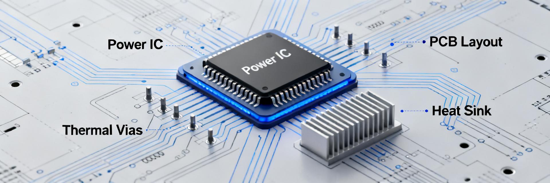
التحليل التفصيلي لورقة بيانات UQDLS-04HSH03-R000: المواصفات الكاملة
مع تضييق هامش كثافة الطاقة والميزانيات الحرارية في التصاميم الأمريكية، يمكن لورقة بيانات المكوّن أن تصنع أو تُفشل اللوحة — يفكّ هذا التحليل العميقUQDLS-04HSH03-R000لمنح المهندسين وفرق المشتريات ومديري المنتجات نظرة موجزة ومدعومة بالبيانات. يشير هذا المقال إلى اللغة الرسمية لورقة البيانات، ويسلط الضوء على المواصفات الحيوية، ويقدّم إرشادات عملية للتنفيذ والاختبار والشراء. النطاق: لمحة سريعة عن المواصفات، تحليل كهربائي وحراري مفصّل، نصائح لتنفيذ اللوحة الإلكترونية، قائمة مراجعة للتحقق، ونصائح للمشتريات. سيحصل القراء على جدول واحد يعرض المعلومات بوضوح، مع مثال حراري عملي (تم وضع قيم نموذجية)، وإجراءات الاختبار، وقائمة مختصرة بأبرز أسباب الفشل مع خطوات للتخفيف منها. الخلفية: ما هو UQDLS-04HSH03-R000 وأين يُستخدم 1.1 لمحة سريعة عن المواصفات (ملخص في جدول واحد) الحقلالقيمة (PLACEHOLDER — استبدلها ببيانات الورقة) عائلة القطعةسلسلة UQDLS العبوة / عدد الأطرافدبابيس QFN / PLACEHOLDER التقييمات الاسمية (فولت / أمبير)Vmax = [V_PLACEHOLDER]، Imax = [I_PLACEHOLDER] نطاق التشغيل النموذجي[من Vmin–Vmax]، [Ityp] المقاومة الحراريةRθJA = [PLACEHOLDER]، RθJC = [PLACEHOLDER] التطبيقات المقصودةتحويل الطاقة، الحماية، التبديل النقطة: يعكس الجدول الحقول الرئيسية في ورقة البيانات لتسهيل اتخاذ القرار السريع. الدليل: تُدرج ورقة البيانات معلومات عن عائلة القطعة، والعبوة، والتقييمات، والمقاومة الحرارية. الشرح: استخدم هذا الجدول السريع لمراجعة قائمة المواد وتحديد الميزانية الحرارية الأولية قبل الاطلاع الكامل على المواصفات. UQDLS-04HSH03 وحدة التحكم / المفتاح VCC IN OUT الحالة EPAD / GND 1.2 حالات الاستخدام النموذجية والتطبيقات المستهدفة النقطة: تشمل التطبيقات الشائعة تحويل الطاقة، الحماية من التغيرات المفاجئة، وتبديل الإشارات. الدليل: تشير ملاحظات التطبيق والقيم المُصنَّفة في دفتر البيانات إلى ملاءمتها للأدوار التي تتطلب مقاومة عالية للنبضات وفقدان منخفض للطاقة. الشرح: اختر هذه القطعة عندما تكون انخفاض الجهد الأمامي، وقدرة التحمل على النبضات، والتغليف المدمج أمورًا مهمة؛ وتحقق من القيم المُصنَّفة والمواصفات الحرارية في دفتر البيانات لتأكيد ملاءمتها لملف الحمل المقصود. تعمق في الخصائص الكهربائية 2.1 المعايير الثابتة: الجهدات والتيارات والحدود النقطة: تمييز القيم القصوى المطلقة عن ظروف التشغيل الموصى بها. الدليل: تحدد جداول دفتر البيانات VMAX، التيار المستمر، التسرب العكسي وظروف الاختبار. الشرح: يجب وضع هامش التصميم باستخدام ظروف التشغيل الموصى بها، وليس القيم القصوى المطلقة؛ واحرص على ملاحظة ظروف القياس (درجة الحرارة المحيطة، عرض النبضة) المطبوعة في دفتر البيانات لتجنب سوء تفسير الحدود. 2.2 السلوك الديناميكي والمؤقت: التبديل، ارتفاع/انخفاض الجهد، أحداث النبضات النقطة: تحدد المقاييس الديناميكية (أوقات التبديل، السعة، مواصفات نبضات التيار المفاجئ) الأداء في العالم الحقيقي. الدليل: توفر رسومات البيانات مقارنة بين القيم النموذجية والحد الأقصى لأوقات التبديل والأمواج العابرة تحت ظروف محددة لجهد الإمداد والحمل. الشرح: عند إجراء التوصيف، يجب إعادة إنتاج شروط الاختبار الواردة في دفتر البيانات وتسجيل أوقات الصعود/الهبوط، واستعادة الانعكاس، وتسرب التيار العابر للتحقق من هامش التصميم. تحليل الحرارة والموثوقية 3.1 مقاييس الحرارة: RθJA، RθJC، منحنيات خفض القدرة النقطة: اقرأ مقاومات الحرارة ومنحنيات التخفيض لحساب درجة حرارة الوصلة. الدليل: يُدرج دليل البيانات قيمتي RθJA وRθJC، كما يقدّم جداول تخفيض الأداء مقابل درجة الحرارة المحيطة وفقًا لظروف محددة للدارة المطبوعة. الشرح: استخدم المعادلة Tj = Ta + P × RθJA. مثال عملي (أرقام نموذجية — يُستبدل): إذا كانت Ta=25°C، وPd=[P_PLACEHOLDER]W، وRθJA=[R_PLACEHOLDER]°C/W، فإن Tj = 25 + P×RθJA = [Tj_PLACEHOLDER]°C؛ وقم بتعديل القيم باستخدام الفتحات الحرارية ومساحة النحاس وفقًا لتوصيات دليل البيانات. 3.2 حدود الموثوقية وعوامل العمر الافتراضي النقطة: بيانات الموثوقية (دورة درجات الحرارة، الرطوبة، ملاحظات MTBF) تُستخدم في تحديد هامش التصميم. الدليل: يحتوي دفتر البيانات على إدخالات اختبار بأسلوب JEDEC ومعايير النجاح/الفشل. الشرح: عند التصميم لتطبيقات طويلة العمر، يجب تطبيق قواعد تخفيض الأحمال والهوامش القياسية الأمريكية للموثوقية (مثل تخفيض التيار ودرجة الحرارة)، مع تسجيل ظروف الاختبار وإمكانية تتبع الدفعة أثناء عملية التحقق. دليل تنفيذ وتصميم اللوحات الإلكترونية 4.1 ملاحظات حول البصمة والتجميع والتعامل مع العبوة النقطة: البصمة والستينسل يؤثران على جودة اللحام والأداء الحراري. الدليل: الرسم الميكانيكي ونمط الأرجل الموصى به موجودان في قسم العبوة بدفتر البيانات. الشرح: يجب اتباع اصطلاح تسمية بصمة Gerber الموصى به، واستخدام نسبة فتحة 0.5–0.6 للوسادات الحرارية، وإضافة فتحات حرارية في الوسادة المكشوفة، بالإضافة إلى اتباع احتياطات التعامل الواردة في دفتر البيانات لتجنب إجهاد العبوة أثناء عملية إعادة الصهر. 4.2 التوبولوجيات الدائرية النموذجية وتكامل قائمة المواد (BOM) النقطة: توضح الدوائر المرجعية مواضع المكونات ودعمها. الدليل: تُظهر مخططات الدوائر المرجعية في دفتر البيانات القيم السلبية المقترحة ومواقع المثبطات. الشرح: ضع مكثفات العزل بالقرب من أطراف الطاقة، واجعل مسار العودة الحرارية مباشرة تحت اللوحة، وحدد المثبطات أو ثنائيات TVS وفقًا لإرشادات التغيرات العابرة في دفتر البيانات لتثبيت حواف التبديل والحماية من حالات الارتفاع المفاجئ. الاختبار، والتحقق، واستكشاف الأخطاء وإصلاحها 5.1 إجراءات الاختبار وقائمة فحص القياس النقطة: يقلل مخطط اختبار المنضدة من المفاجآت أثناء التكامل. الدليل: يحدد دفتر البيانات حدود النجاح/الفشل وظروف اختبار الموجات. الشرح: تشمل الأدوات المطلوبة مسبارًا بتردد 100 ميجاهرتز فأكثر، وجهاز قياس المصدر، وكاميرا حرارية، ومزود طاقة مختبري؛ مع التقاط قيم الجهد/التيار في الحالة المستقرة، والموجات العابرة، ودرجة حرارة الوصلة ضمن ظروف اختبار دفتر البيانات؛ وتوثيق التفاوتات ومقارنتها بالمواصفات. 5.2 أنماط الفشل الشائعة ونصائح تصحيح الأخطاء (دراسة حالة مصغرة) النقطة: من الأعطال الشائعة ارتفاع درجة الحرارة، التسرب، وشذوذات التبديل. الدليل: تشير حدود دليل البيانات والمنحنيات الحرارية إلى الحساسية تجاه تصميم اللوحة والارتفاع المفاجئ في الجهد. الشرح: يمكن التخفيف من هذه المشكلات بزيادة مساحة النحاس، إضافة الفيَّات، فرض تخفيض الحمل، إضافة أجهزة تثبيت التذبذب، والتحقق باستخدام التصوير الحراري؛ وفي حالة استعادة مجهولة المصدر: تم الاستبدال بزيادة عدد الفيَّات وتقليل المقاومة الحرارية للنحاس لحل مشكلة الانقطاع الحراري. قائمة التحقق للمشتريات، البدائل، والامتثال 6.1 قائمة التحقق من الشراء ومطابقة المواصفات للمشتريات النقطة: يجب على قسم المشتريات التحقق من علامة القطعة، رموز الطلب، وطريقة التعبئة. الدليل: تُحكم معلومات الطلب في دليل البيانات والمواصفات الميكانيكية اختيار القطعة الصحيحة. الشرح: يُرجى إدراج مرجع دليل البيانات ورمز القطعة الدقيق في أوامر الشراء، والتأكد من الحد الأدنى لكمية الطلب ووحدة التعبئة، والتحقق من توافق المواصفات الحرارية والكهربائية مع التطبيق المقصود قبل إصدار أمر الشراء. 6.2 الإشارات المتبادلة وكيفية تقييم البدائل النقطة: المواصفات الأساسية التي يجب مطابقتها هي الحدود الكهربائية، والغلاف، والأرقام الحرارية. الدليل: مقارنة أوراق البيانات لأعضاء العائلة المتشابهين تبرز أي المعايير تُقايض ببعضها البعض. الشرح: اصنع شجرة قرار مختصرة: مطابقة الغلاف وRθJA → مطابقة حدود الجهد/التيار → التحقق من صحة المواصفات الديناميكية والطارئة؛ قم بإنشاء نموذج أولي وإعادة تنفيذ قائمة الفحص عند استبدال الأجزاء. ملخص رئيسي UQDLS-04HSH03-R000مواصفات سريعة: تحقق من الغلاف، وتصنيفات الجهد/التيار، وRθJA من ورقة البيانات قبل تثبيت قائمة المواد؛ وتحقق بشكل متقاطع من متطلبات الوسادة الحرارية لانتشار الحرارة على مستوى اللوحة. فحوصات كهربائية وطارئة: تأكد من المقارنة بين القيم القصوى المطلقة والظروف التشغيلية الموصى بها، وقم بإعادة إنتاج ظروف اختبار الموجات من ورقة البيانات أثناء التحقق لتجنب سوء التفسير. التنفيذ والاختبار: اتبع الإرشادات الخاصة بالبصمة المعتمدة، وأضف فتحات حرارية، واستخدم مخففات أو عوازل وفق المخططات المرجعية، وقم بتشغيل قائمة الفحص على المنضدة للتحقق من الأداء. الملخص / الاستنتاج تلخيص: الـUQDLS-04HSH03-R000يتفوق في الحالات التي تتطلب تصميمًا حراريًا مدمجًا وسلوكًا عابرًا قويًا؛ ومن أهم الفحوصات الواجب إجراؤها المقاومة الحرارية، وحدود التشغيل، ومواصفات التيار العابر الديناميكي الواردة في ورقة البيانات. الإجراء: قم بتنزيل ورقة البيانات الرسمية، وطبق مخطط تخطيط اللوحة الإلكترونية وخطوات التخفيف الحراري، ثم قم بتنفيذ قائمة الفحص المقدمة قبل بدء الإنتاج. أسئلة شائعة ما هي النقاط الرئيسيةUQDLS-04HSH03-R000العناصر التي يجب التحقق منها في ورقة البيانات قبل الشراء؟ تحقق من حزمة المكون ونمط الأرجل، والأرقام الحرارية RθJA/RθJC، وتصنيفات التيار المستمر والذروة، وأقصى جهد مطلق، وأي تصنيفات للتيارات العابرة أو النبضات المحددة. كما ينبغي تضمين رموز الطلب والتحقق من الرسومات الميكانيكية في وثائق الشراء لتجنب أخطاء الشحن الخاطئ. كيف ينبغي للمهندسين التحقق منUQDLS-04HSH03-R000الأداء الحراري على لوحة الدوائر المطبوعة؟ استخدم ورقة البيانات RθJA ومنحنيات تقليل التحميل كنقطة انطلاق، ثم قم بقياس درجة حرارة الوصلة تحت تبديد الطاقة المتوقع باستخدام كاميرا حرارية ومقاييس حرارية مدمجة. زد مساحة النحاس أو الفيَّات إذا تجاوزت Tj الهامش المستهدف، وأعد القياسات وفقًا لقائمة فحص الاختبار. ما هي اختبارات ورقة البيانات التي تمنع المفاجآت عند الدمج معUQDLS-04HSH03-R000؟ أعد إنشاء ظروف اختبار الحالة العابرة والحالة المستقرة كما في ورقة البيانات: التقاط الموجات للحوادث أثناء التبديل، واختبارات الارتفاع المحدودة بعرض النبضة، والتسرب عند درجة حرارة محددة، ودرجة حرارة الوصلة تحت القدرة المقدرة. قارن القيم المقاسة بحدود النجاح/الرسوب في ورقة البيانات ووثق الانحرافات قبل الموافقة النهائية. ما هي تدابير التخطيط الحراري التي تعد أساسية لمنع انقطاع الدائرة بسبب الحرارة علىUQDLS-04HSH03-R000؟ قم بتطبيق نسبة فتحة الاستنسل بين 0.5 و0.6 للألواح الحرارية المكشوفة، وضع فتحات حرارية ذات كثافة عالية عبر الثقوب مرتبطة مباشرةً بطبقات الأرض الداخلية، وقم بوضع مكثفات الفصل للمدخلات بجوار دبابيس التغذية لتقليل حث الحلقة عند الترددات العالية إلى أدنى حد.
Copyright@2026 All Rights Reserved
ICP Filing No.: 粤ICP备2026080158号


