





The AV87-15J4AWN family addresses a growing demand for higher-density, ruggedized fiber interfaces in aerospace and defense, where predictable mechanical, environmental, and optical performance is mandatory. This datasheet-focused walkthrough distills the critical fields engineers and procurement teams must validate: configuration coding, mechanical footprints, materials and finishes, environmental ratings, optical loss budgets, and termination practice. The goal is a practical, spec-driven checklist to reduce integration risk and shorten qualification cycles.
1 — Quick product snapshot: what the AV87-15J4AWN connector is and where it fits (background)
1.1 — One-line summary + primary applications
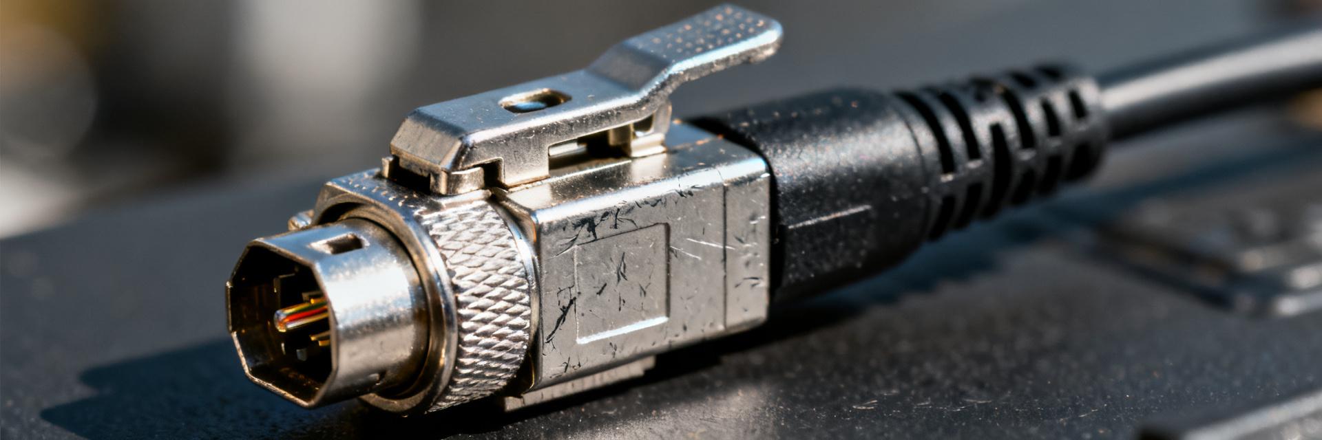
One-line summary (from the manufacturer datasheet): a rugged, MIL-style multi-fiber optical connector optimized for high-density, environmentally sealed fiber interconnects in harsh platforms. Primary target applications include military/aerospace avionics, rugged communications shelters, shipboard systems, and mobile ground vehicles where shock, vibration, and ingress protection drive connector selection decisions. The AV87-15J4AWN connector is intended for system integrators needing repeatable optical performance in controlled mating cycles.
1.2 — Available configurations and naming breakdown
The model code encodes shell size, contact/port count, insert type, guide/ferrule style, and coupling mechanism. Typical datasheet fields map a prefix/suffix pattern to attributes: shell size → mechanical envelope; numerals → insert density; letters → ferrule/insert type; final letters → coupling and finish. A concise code-to-meaning table clarifies ordering options and reduces mis-picks during procurement.
- Code segment → meaning: shell size (numeric)
- Code segment → meaning: insert/fiber count (numeric)
- Code segment → meaning: coupling style and finish (alpha)
| Code Field Segment | Value Type | Component & Attribute Mapping |
|---|---|---|
| AV87 | Alphanumeric Prefix | Product Series / Standard MIL-Style Architecture |
| 15 | Numeric Standard | Shell Size Envelope & Mechanical Footprint |
| J4 | Alphanumeric Insert | Insert Density / Total Fiber Channel Count |
| AWN | Alpha Suffix | Coupling Profile, Contact Geometry, Finish Coating |
2 — Mechanical specifications & mounting details (data analysis)
2.1 — Shell, dimensions, footprint and panel cutout
Critical mechanical drawings to extract: overall shell size, panel cutout outline, mating-face profile, keying orientation, and mounting style (jam-nut or flange receptacle). The datasheet's outline and tolerance block supply nominal and max/min values for mating depth, shell diameter, and screw patterns. Capture these values in a critical-dimensions table with units (inches for US market) and verify mating clearance and board/component interference before creating panel CAD.
2.2 — Materials, finishes, and corrosion resistance
Datasheet material fields identify shell alloy, insert thermoplastic, ferrule composition, and plating or conversion coatings. Typical finishes include electroless nickel, passivated aluminum, or corrosion-resistant platings; each finish is recommended per exposure profile. Select higher-corrosion finishes (e.g., nickel over passivation) for salt-fog or maritime environments and lower-weight finishes where weight and conductivity matter.
3 — Environmental & performance ratings (data analysis)
3.1 — Temperature, shock, vibration, and sealing
Extract operating and storage temperature ranges, shock and vibration test levels, and any sealing or IP-equivalent statements. Present a table mapping test type → requirement → referenced test standard (e.g., MIL shock waveform, random vibration g RMS, ingress sealing pressure). These numeric limits directly inform qualification planning and environmental stress screening for assemblies using this connector family.
3.2 — Reliability metrics and lifecycle
Key reliability metrics in the datasheet include specified mating cycles and any MTBF or failure-mode notes. Mating-cycle counts provide a baseline for maintenance scheduling; for example, a 500-cycle rating supports multiple field replacements but requires inspection protocols. Use mating-cycle figures to size spare-part inventory and to define preventive maintenance intervals for fielded systems.
4 — Optical & electrical characteristics (data analysis)
4.1 — Optical performance: insertion loss, return loss, ferrule type
Optical metrics to pull from the datasheet are typical and maximum insertion loss per mate, return loss (ORL), ferrule/fiber alignment features (MT ferrule, MT-RJ, etc.), polish type, and test conditions (wavelengths and fiber type). As shown in the datasheet, present both typical and worst-case insertion loss values and note test wavelengths (e.g., 850/1300 nm or single-mode 1310/1550 nm). Clarify test jigs and reference fibers used to ensure apples-to-apples comparisons with system budgets.
4.2 — Electrical/grounding features (if hybrid) or optical-only notes
If the part includes hybrid electrical contacts or grounding shells, list contact arrangements, current ratings, and ground continuity methods. If the connector is optical-only, state that explicitly and explain harnessing implications: separate grounding hardware will be required and cable strain relief points must be coordinated to maintain optical alignment and sealing.
5 — Termination, assembly and maintenance (method guide / case)
5.1 — Field termination and factory termination steps
Termination workflow: prepare and strip cable, cleave and clean fibers, insert ferrules into the insert, secure retention/strain relief, and verify polish/physical connection. Required tools include precision cleaver, fiber scribe, cleaning solvents, and controlled torque driver for coupling nuts. Common pitfalls are inadequate cleave quality, contamination during insertion, and over-torquing retention clamps—use a step checklist and sampling acceptance criteria to avoid rework.
5.2 — Torque, mating/unmating procedures, and inspection
Follow specified torque values for coupling rings and mounting hardware; the datasheet provides recommended torque ranges for repeatable mating. Inspection should include visual ferrule inspection, insertion-loss or power-meter checks, and OTDR spot checks after assembly. Document torque points and inspection views so field technicians can reproduce factory-quality mates under operational constraints.
6 — Standards, compatibility, procurement checklist & selection guidance (action)
6.1 — Applicable standards and cross-compatibility
List the MIL and optical interface standards referenced by the datasheet and confirm mechanical compatibility with mating plugs/receptacles by checking shell size, keying, insert type, and ferrule geometry. A decision tree should confirm three items in order: shell size match, insert/fiber count match, and keying/polarity match. Resolve any mismatch before issuing purchase orders to prevent incompatible deliveries.
6.2 — Procurement checklist & recommended questions for vendors
Buyer checklist: request the full datasheet PDF, lot traceability, sample test reports, chosen plating option, lead times, MOQ, and tooling/termination requirements. Ask vendors for confirmation of mating-cycle test results and environmental test certificates. Useful vendor search phrases include long-tail terms such as “AV87-15J4AWN connector datasheet PDF” and “AV87-15J4AWN connector dimensions” to ensure you retrieve the exact spec sheet and associated drawings.
Summary (conclusion and next steps)
Validating the AV87-15J4AWN connector datasheet fields up front—mechanical envelope, materials/finish, environmental ratings, optical loss budgets, and termination procedures—reduces integration risk and shortens qualification time. Prioritize dimensional drawings, optical test conditions, mating-cycle limits, and finish options during procurement to avoid late-stage surprises. Next step: download the official datasheet PDF and run a quick compatibility checklist against your platform CAD and optical budget.
- Confirm mechanical envelope and panel cutout match system CAD, including keying and mounting style; mismatches cause costly rework.
- Verify optical specs—typical vs. maximum insertion loss and test wavelengths—to ensure the connector meets the system loss budget.
- Choose material/finish based on environmental exposure and request test reports for corrosion or salt-fog where required.
Frequently Asked Questions
What are the primary applications of the AV87-15J4AWN connector?
The AV87-15J4AWN is optimized for high-density, environmentally sealed optical interconnections in military and aerospace systems, including avionics, rugged communications shelters, mobile ground vehicles, and shipboard platforms.
How is the AV87-15J4AWN part code decoded?
The part number encodes critical shell physical attributes: shell size (numeric), insert/fiber density/count (numeric), and the specific coupling style and surface finish configuration (alpha).
What are the key optical specifications for insertion loss?
The connector is designed to meet strict typical and worst-case insertion and return loss limits across targeted wavelengths (e.g., 850/1300 nm multi-mode or 1310/1550 nm single-mode) when paired with standard reference fibers.
What is the recommended maintenance protocol for this optical connection?
Proper field maintenance requires visual ferrule inspection using a fiber microscope, strictly verifying torque values during mating, clean-up using optical-grade solvents, and regular power-meter or OTDR sweeps.


