





Industry adoption of UQD-style quick disconnects has risen steadily in hyperscale racks and dense server enclosures, with estimated deployments reaching into double-digit percentages of new rack installs and typical loop flow rates spanning 0.5–25 L/min (0.13–6.6 GPM) depending on bore size. This brief, datasheet-style summary defines the UQD connector, lays out the essential key specs and flow data engineers need, and provides selection, testing, and installation checks to accelerate procurement and commissioning.
The goal is a concise technical reference that complements a full datasheet: extract form-factor and sealing norms, list mechanical and hydraulic parameters, show representative flow ranges and pressure-drop expectations, and finish with practical checklists for spec writers and test engineers.
1 — UQD connector: overview & design intent (Background)
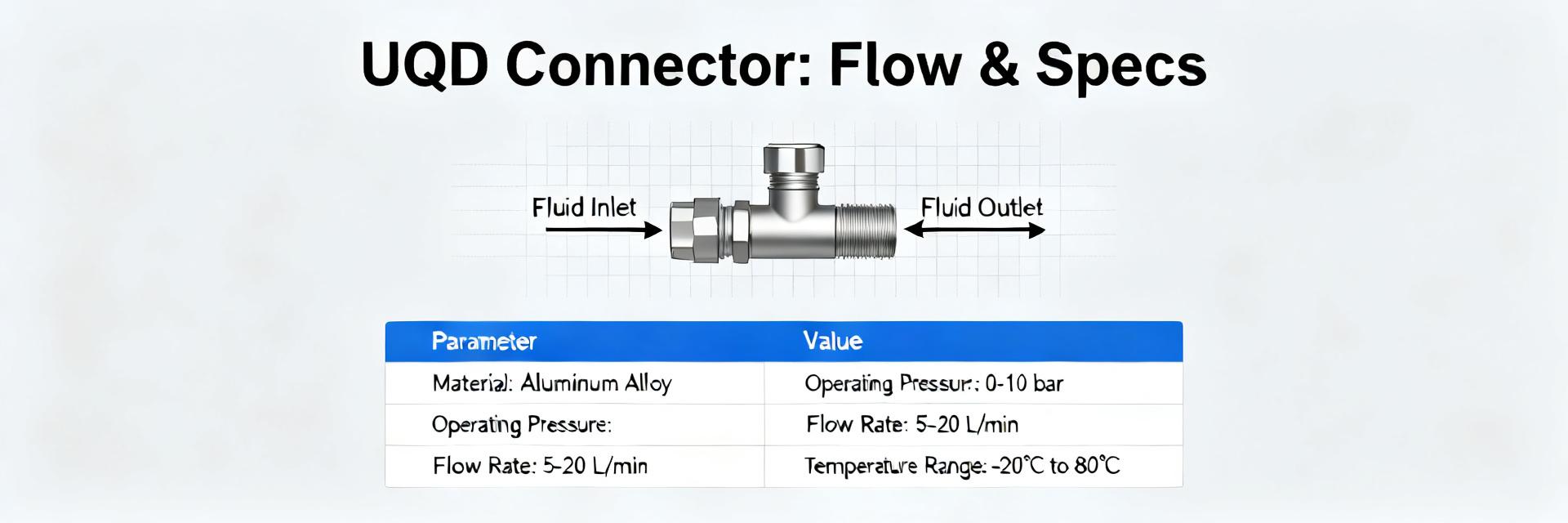
Form factor, standards and nominal sizes
Point: UQD connectors follow an industry-standard blind-mate quick-disconnect form optimized for rack liquid-cooling. Evidence: common nominal bores span approximately 2.5 mm to 12 mm ID (0.10–0.47 in) with mating faces offered in flat-face non-spill or low-drip variants. Explanation: a datasheet should list nominal bore, OD references, face style, coupling geometry, and dimensional tolerances (typical ±0.1 mm for critical diameters, concentricity & flatness tolerances for sealing faces) to ensure interchangeability and proper blind-mate alignment.
Core functions and typical thermal-management use cases
Point: The UQD connector is designed for single-phase liquid cooling loops—water, water/glycol mixes, and specialized dielectric coolants—and to minimize fluid loss on mate/unmate. Evidence: key valve mechanisms close on unmating to reduce spills and open when fully engaged; datasheet and key specs capture valve actuation sequence and residual volume per disconnect. Explanation: this behavior enables safe rack swaps, hot-swap maintenance, and predictable loop balancing in data-center thermal-management architectures.
2 — Key specs at a glance (Datasheet breakdown)
Mechanical & material specs to report
Point: A complete datasheet must enumerate construction materials and mechanical limits. Evidence: mandatory fields include body material and plating, seal polymer type, nominal diameter, coupling type, orientation, max working pressure, proof and burst pressures, operating temperature range, and recommended mating torque or axial force. Explanation: report pressures in bar and psi, temperatures in °C and °F, and torque in N·m and lbf·ft; typical value ranges: working pressure 10–40 bar (150–600 psi), proof 1.5× working, burst ≥3× working, temp −40 to +120 °C (−40 to +248 °F) depending on seals.
Hydraulic & sealing specs
Point: Hydraulic performance and leak criteria are central to selection. Evidence: datasheets should provide Kv or Cv, leak rates for dry/gas/wet conditions, and coolant compatibility listings (percent glycol, DI water, dielectric fluids). Explanation: present Kv/Cv (m³/h or GPM at 1 bar/psi reference), specify allowable wet-leak threshold (e.g., <0.1 mL/min under pressure), and include a compatibility table so designers can quickly compare connectors for a given coolant.
3 — Flow data & performance curves (Data analysis)
Typical flow rates by size and expected pressure drop
Point: Size drives achievable flow and ΔP; datasheets must offer compact reference tables. Evidence: example ranges — 2.5 mm ID: 0.5–1.5 L/min (0.13–0.4 GPM) with ΔP 5–25 kPa (0.7–3.6 psi); 6 mm ID: 3–8 L/min (0.8–2.1 GPM) with ΔP 5–50 kPa (0.7–7.2 psi); 12 mm ID: 10–25 L/min (2.6–6.6 GPM) with ΔP 10–100 kPa (1.5–14.5 psi). Explanation: include max continuous flow recommendation (typically set by allowable ΔT and pump head), and surge limits (short-term peak flows 1.5–2× continuous rating) to prevent erosion or valve chatter.
How to read and interpolate flow curves
Point: Users must be able to interpolate between published curves for different viscosities and temperatures. Evidence: provide Cv/Kv plus a representative Q vs. ΔP curve family (lines per viscosity) and a small lookup table for intermediate points. Explanation: plot flow (L/min or GPM) on the x-axis and pressure drop (kPa or psi) on the y-axis, include curve families for 1 cP (water), 10 cP, and 50 cP; interpolation between curves is linear in log–log space for rough estimates, with a sample calculation shown.
4 — Selection & compatibility checklist (Method / practical guide)
Match size, pressure rating and media compatibility
Point: Follow a stepwise match process to avoid field failures. Evidence: checklist items — verify nominal bore vs. system flow; confirm max working pressure and temperature margins; verify seal polymer compatibility with coolant; check wetted-material galvanic pairs and plating. Explanation: include long-tail procurement phrases (e.g., “nominal 6 mm ID UQD, EPDM seals compatible with 30% ethylene glycol, stainless-steel 316 body, max working pressure 25 bar”) so buyers can paste into RFPs.
Safety, leak mitigation and operational limits
Point: Specify margins and operational thresholds for safe service. Evidence: recommend safety factor of 1.3× working pressure for system design, leak-detection sensitivity (e.g., ≤0.1 mL/min wet or ≤1×10⁻³ mbar·L/s gas), and cycle-life or service lifespan (e.g., >5,000 mating cycles or time-based replacement interval). Explanation: include cycle ratings and required detection thresholds on the datasheet to align operations with facility monitoring and maintenance plans.
5 — Installation, testing & maintenance best practices (Method)
Mating/unmating procedure and inspection criteria
Point: Standardize mate/unmate procedures to limit damage and leaks. Evidence: list steps — inspect face and seals visually, clean if required, align blind-mate guide, apply rated axial force until positive stop or torque spec met; post-mate verify no external leakage at operating pressure. Explanation: note visual criteria (no nicks on sealing face, seal compression uniformity), specify any required tools and torque verification methods (torque wrenches or calibrated push fixtures) for field teams.
Factory and field test recommendations
Point: Define acceptance and periodic tests to validate integrity. Evidence: recommend dry gas and wet pressure tests: factory proof at 1.5× working pressure for 1 min, field commissioning at working pressure with leak-rate acceptance, and periodic pressure-checks during maintenance. Explanation: list acceptable test pressures (e.g., commissioning 1.0× working for 5 min, allowable wet leak <0.1 mL/min) and suggest a test frequency tied to duty (monthly for active swap zones, annually otherwise).
6 — Application examples & quick spec reference (Case + Action)
Two short application scenarios with spec picks
Point: Example-driven picks speed decisions. Evidence: Scenario A — high-density single-rack cooling loop: choose 6 mm ID UQD, Kv ≈ 0.15 m³/h (0.88 Cv), target flow 6 L/min (1.6 GPM), working pressure 25 bar, EPDM seals; rationale: balances low ΔP with minimal leak volume for hot-swap racks. Scenario B — mid-density multi-rack distro: choose 12 mm ID UQD, Kv ≈ 0.45 m³/h (2.6 Cv), flow 18 L/min (4.8 GPM), working pressure 16 bar, FKM seals. Explanation: each pick ties nominal size to flow target and pressure margin for procurement clarity.
Quick spec reference table & procurement checklist
Point: Provide a copy-paste-ready template for RFPs and BOMs.
| Nominal Size | Kv / Cv Rating | Max Working Pressure | Temperature Range | Standard Seal Material | Leak-Rate Threshold |
|---|---|---|---|---|---|
| 2.5 mm ID | 0.03 Kv / 0.17 Cv | 40 bar (580 psi) | -40°C to +120°C | EPDM / FKM | <0.05 mL/min (wet) |
| 6.0 mm ID | 0.15 Kv / 0.88 Cv | 25 bar (362 psi) | -40°C to +120°C | EPDM / Silicone | <0.10 mL/min (wet) |
| 12.0 mm ID | 0.45 Kv / 2.60 Cv | 16 bar (232 psi) | -20°C to +150°C | FKM / HNBR | <0.15 mL/min (wet) |
Explanation: conclude with a short actionable procurement checklist: verify certificate of conformity, request factory test reports, confirm spare-parts availability and lead time before contract award.
Summary
- UQD connector selection hinges on matching nominal bore to system flow and checking Kv/Cv and pressure ratings; datasheet entries should always list these key specs along with seal materials.
- Provide Kv/Cv plus representative flow curves and a compact flow table so engineers can size for ΔP and pump head across coolant viscosities and temperatures.
- Include mechanical limits (working/proof/burst), material/plating and seal compatibility, plus cycle rating and leak thresholds to support procurement and operations.
Recap: this compact, data-driven datasheet summary is intended to accelerate specification, selection, and testing of UQD connector choices for thermal-management systems. Prioritize the most critical key specs—size, Kv/Cv, max pressure, temperature range, and material/seal—when writing procurement documents and commissioning tests to reduce risk and speed deployment.
FAQ: What should I check first when specifying a UQD connector?
Start by matching nominal bore and Kv/Cv to your required system flow and allowable pressure drop, then confirm max working pressure and temperature margins. Verify seal polymer compatibility with your coolant and confirm the stated leak-rate thresholds and cycle rating on the datasheet before procurement.
FAQ: How do I interpret Kv/Cv values in a UQD connector datasheet?
Kv (m³/h at 1 bar) or Cv (GPM at 1 psi) indicate flow capacity; use these with the target flow to estimate pressure drop. For intermediate conditions, use the published flow curve or interpolate between curve families for the coolant viscosity and temperature to predict ΔP accurately.
FAQ: What factory tests should be required for UQD connectors?
Request factory proof-pressure testing (typically 1.5× working pressure) and wet-leak validation at working pressure with documented leak rates. Ask for serial-linked test reports, material certificates, and any cycle-life test data to ensure components meet operational and safety expectations.
FAQ: What are the typical flow rates for UQD connectors by size?
Typical flow rates span 0.5–25 L/min (0.13–6.6 GPM) depending on nominal bore size. Specifically: 2.5 mm ID handles 0.5–1.5 L/min; 6 mm ID handles 3–8 L/min; and 12 mm ID handles 10–25 L/min.


