





Benchmarks for UQD06-style quick disconnects consistently show tight flow stability and predictable pressure behavior across typical liquid-cooling ranges, making accurate part-level specifications essential for reliable system design. This document provides a concise, actionable full datasheet-style breakdown for UQDP-06TMB03-R000, covering identification, physical and material notes, hydraulic flow guidance, installation and maintenance checks, and field troubleshooting.
Product overview & key identification (background)
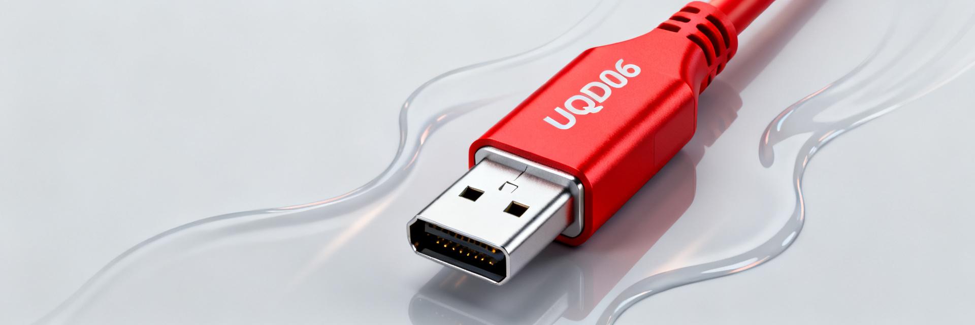
Basic part ID & nomenclature
Point: The part string encodes family, size, interface, thread type and color coding; understanding each segment avoids procurement and compatibility errors. Evidence: In common UQD families, prefixes denote plug or socket, the numeric token indicates size class, and the trailing code indicates thread and color. Explanation: For planning, treat the string as modular: family → size → interface/thread → color/variant; verify exact thread callout when ordering.
| Part number | Family | Interface type | Color | Typical use |
|---|---|---|---|---|
| UQDP-06TMB03-R000 | UQD06 | Universal quick-disconnect, male threaded | Red | Liquid-cooling quick connect for rack and bench plumbing |
Intended applications & compliance highlights
Point: UQD06-family connectors are optimized for liquid-thermal systems requiring rapid connect/disconnect. Evidence: Typical deployments include data-center rack manifolds, cold-plate feeds, and modular test loops. Explanation: Design teams should map connector Cv, thread compatibility and seal materials to target coolant chemistry and any relevant open-compute or data-center thermal guidance when specifying system acceptance.
Physical & materials specifications
Dimensional data & thread/interface details
datasheet point: Accurate dimensions and thread form are essential for sealed mating and acceptable tolerance stacks. Evidence: Key dimensions to capture are overall length, nominal outside diameter, thread format and pitch, sealing face geometry, and recommended mating tolerance. Explanation: Include a labeled dimension diagram and a CAD download note so mechanical teams can validate clearance and panel cutouts before procurement.
| Dimension | Symbol | Value (mm / in) | Tolerance |
|---|---|---|---|
| Overall length | L | Verify with vendor | ± see vendor drawing |
| Nominal diameter | D | Verify with vendor | ± see vendor drawing |
| Thread spec | Thread | Commonly BSP or specified metric; verify exact pitch | Per thread standard |
| Sealing surface | S | Flat face or tapered; verify geometry | Per drawing |
Materials, surface finish & environmental ratings
Point: Material and finish selection dictates fluid compatibility and longevity. Evidence: Wetted components in UQD families are typically corrosion-resistant alloys or plated metals; non-wetted housings may use alternate alloys or coatings. Explanation: For final selection consult the official datasheet for wetted-material callouts, surface finish, operating temperature range, and recommended seal elastomers (e.g., EPDM, FKM) based on coolant chemistry.
Hydraulic performance & flow data (data analysis)
Nominal flow, Cv/Kv, and pressure drop curves
Point: Designers need Cv/Kv and flow-vs-ΔP curves to size pumps and manifolds. Evidence: Present Cv or Kv in the datasheet alongside measured flow points and a plotted curve; typical reporting uses water at 20°C (viscosity ~1 cP) on the test rig. Explanation: For UQDP-06TMB03-R000 produce a curve of flow (L/min or GPM) vs. ΔP (bar or psi) and include measurement method: test fluid, temperature, rig back-pressure, and measurement accuracy.
| ΔP (bar) | Flow (L/min) |
|---|---|
| 0.5 | Verify measured value |
| 1.0 | Verify measured value |
| 2.0 | Verify measured value |
Measurement method note: Use distilled water at ~20°C, calibrated flow meter, steady-state readings after warm-up; document sensor uncertainty and rig configuration on the test report. Include plotted graph (flow on X, ΔP on Y) in published datasheet.
Maximum working pressure, burst, and leak thresholds
Point: Pressure ratings and leak acceptance criteria govern safe operation. Evidence: Datasheet sections should state maximum continuous working pressure, recommended safety margin (e.g., % of burst), burst pressure, and allowable leak rate (mL/min). Explanation: When temperature or alternative fluids increase permeation or degrade seals, derate the working pressure and use the datasheet's service-temperature curves; include a recommended pressure-test procedure and pass/fail leak thresholds.
Installation, testing & maintenance (method guide)
Installation & torque/assembly best practices
Point: Correct assembly prevents leaks and extends seal life. Evidence: Pre-checks should include cleanliness, O-ring inspection, and mating-thread verification; alignment and controlled engagement avoid cross-threading. Explanation: Field guidance: clean and inspect, hand-start threads, ensure O-ring seats in groove, tighten to specified torque in the official datasheet or hand-tight plus a prescribed fraction turn; use color-code cues to confirm mate alignment and avoid over-torque that deforms sealing faces.
- Installation checklist: clean ports; inspect O-ring; hand-start threads; seat, then apply specified torque or manufacturer guidance; confirm color-code match.
- Warnings: avoid cross-threading; prevent particulate contamination; do not reuse damaged seals.
Routine testing, service intervals & replacement parts
Point: Scheduled inspection and spares reduce downtime. Evidence: A practical maintenance plan lists leak-test intervals, O‑ring replacement cadence based on duty cycle, and recommended spares. Explanation: Recommend periodic pressure/soak leak tests after installation and at planned service windows; keep on-hand O-rings, dust caps and a spare coupling. Refer to the part datasheet for exact replacement-part numbers and service-life expectations.
Compatibility, use cases & troubleshooting (case & action)
Typical system compatibility & example configurations
Point: Compatibility checks ensure threaded and hydraulic match across system components. Evidence: Example pairings include rack manifold feed, cold-plate supply/return, and modular test-loop ports; adapters may bridge thread or size mismatches. Explanation: Use a short compatibility checklist: thread form, Cv/Kv alignment, seal elastomer compatibility with coolant, and max service temperature. Include topology callouts for common layouts (manifold → quick disconnect → flexible line).
- Topology: rack manifold to cold-plate feed using UQD quick disconnects for field serviceability.
- Topology: modular test loop with a pair of UQD connectors for rapid interchange of DUTs.
Troubleshooting checklist & quick fixes
Point: Rapid isolation of faults reduces mean time to repair. Evidence: A symptom→cause→check→remedy matrix helps field techs resolve issues quickly. Explanation: Use a one-column quick-reference table showing symptom, likely cause and immediate action; escalate to component replacement if leak persists after reseating and seal replacement.
| Symptom → Likely cause → Immediate check → Remedy |
|---|
| Leak at coupling → O-ring out of seat → Inspect O-ring seating and cleanliness → Disassemble, clean, replace O-ring, reassemble |
| High pressure drop → Partial obstruction or wrong Cv → Check for debris and verify Cv → Clean or replace coupling, verify system Cv balance |
Summary (conclusion & datasheet takeaway)
UQDP-06TMB03-R000 is a UQD06-family quick disconnect designed for modular liquid-cooling applications where rapid serviceability and predictable hydraulic behavior matter. Key design choices center on confirmed thread compatibility, verified Cv/Kv or flow curve, and seal elastomer matched to coolant chemistry. For deployment, prioritize the datasheet's pressure ratings, torque guidance and a simple spare-parts kit to minimize downtime.
Key summary
- Confirm thread and interface: verify the UQD06 family, thread pitch and color code match installed plumbing; mismatches create leaks or cross-thread risk.
- Hydraulic design: obtain verified Cv/Kv and plot flow vs. ΔP using the manufacturer-tested rig parameters (water @ ~20°C) before pump selection.
- Installation & maintenance: follow pre-checks, seat O-rings properly, use specified torque or hand-tight procedure, and keep O-ring spares and dust caps on-hand.
Frequently Asked Questions
What are the primary flow characteristics of UQDP-06TMB03-R000?
Nominal flow characteristics should be taken from the validated flow-vs-pressure curve in the official test report: check Cv/Kv values and measured points at representative ΔP (e.g., 0.5, 1.0, 2.0 bar). Use the vendor's test-method appendix (fluid, temperature, rig) to convert to system units and size pumps appropriately.
How should a field tech test for leaks after installing a UQD connector?
Perform a pressure-soak test at the recommended acceptance pressure (see datasheet), visually inspect the sealing face and O-ring, and measure leak rate with a calibrated collection or flow meter. Immediate remedies: depressurize, reseat or replace O-ring, clean mating surfaces, then re-test. Escalate if leak rate exceeds specified acceptance criteria.
Which seal materials are appropriate for common coolants used with these connectors?
Seal choice depends on coolant chemistry and maximum service temperature. Common elastomers include EPDM for glycol-based mixtures and FKM for some synthetic fluids; verify compatibility in the connector's datasheet and perform material-compatibility testing for nonstandard fluids before long-term use.
What is the key identification nomenclature of the UQDP-06TMB03-R000?
The model denotes: UQDP (UQD Plug/Male), 06 (size class 6), TMB03 (thread/interface specification), and R000 (Red color-coded variant).


